


-31-
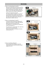
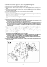
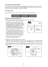
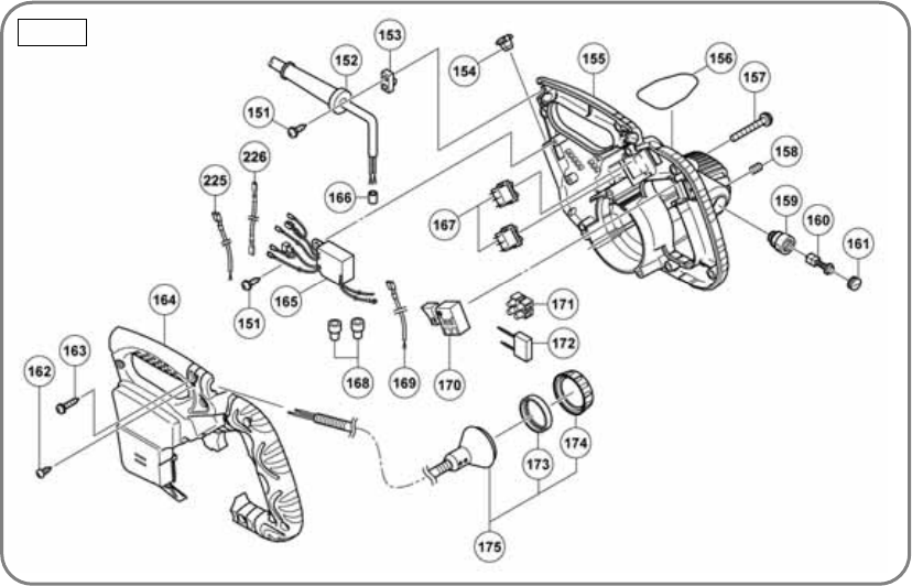
5. Handle cover, switch, light, cord, stator ass'y and housing ass'y
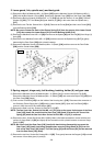
(1) Remove the motor section according to the above step 4-(1)(2).
(2) Remove the seven Tapping Screws (W/Flange) D4 x 20 (Black) [163] and remove the Handle Cover
[164].
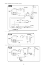
(3) Disconnect the connectors of the Switching Power Supply Ass’y [165] and Light (H) Ass’y [175] and
remove Light (H) Ass’y [175].
(4) Turn Cap (A) [174] and remove it, then you can remove the Clear Cover [173].
(5) (For the U.S.A. and Canada)
Cut off the two Connectors [168] that are crimped onto the internal wires coming from the Stator Ass'y
[181] and the Switch (3P Faston Type) W/O Lock [170].
(Except for the U.S.A. and Canada)
Loosen the screw of Pillar Terminal(A) [171] with a flatblade screwdriver and disconnect the internal
wires.
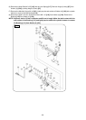
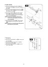
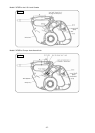
(6) Removal of the Switch (3P Faston Type) W/O Lock [170]:
(a) Remove the Handle Cover [164] from the Housing Ass'y [155] according to the above step 5-(1)(2).
Then the Switch (3P Faston Type) W/O Lock [170] can be removed.
(b) The Stator Ass’y [181] and Internal Wire (G) [169] are provided with a claw to prevent coming off of
the connector. When removing the Stator Ass’y [181] and Internal Wire (G) [169] from the Switch
(3P Faston Type) W/O Lock [170], pull out the Stator Ass’y [181] and Internal Wire (G) [169] while
pressing the claw.
(7) Disconnect the faston of the Switching Power Supply Ass’y [165] from the two Switches (W/Cover)
[167] for the Laser Marker [107] and Light (H) Ass’y [175]. Push the Switch (W/Cover) [167] from the
inside of the Housing Ass’y [155] and remove the Switch (W/Cover) [167].
(8) Remove the Tapping Screw (W/Flange) D4 x 16 [151] and remove the Switching Power Supply Ass’y
[165] from the Housing Ass’y [155].
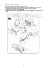
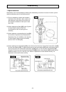
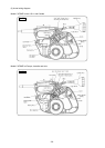
(9) Removal of the Stator Ass’y [181]:
(a) Remove the Fan Guide [178] from the Housing Ass’y [155].
(b) Remove the two Hex. Hd. Tapping Screws D4 x 60 [179] that secure the Stator Ass’y [181] to the
Housing Ass’y
[155]. Remove the two Brush Terminals [180] from the Brush Holder [159].
(c) Pull out the Stator Ass’y [181] by lightly tapping the Housing Ass’y [155] at the surface where the
Gear Case [198] is mounted with a plastic hammer.
(10) Remove the two Tapping Screw (W/Flange) D4 x 16 [151] and remove the Cord [110] and the Cord
Armor D10.1 [152].
Fig. 43