


-33-
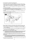
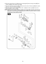
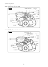
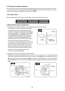
Cross section viewed from the front
1. Special attention
Reassembly can be accomplished by following the disassembly procedures in reverse. However, special
attention should be given to the following items.
(1) Prior to reassembly, measure the insulation
resistance of the armature, stator, switch and
other electrical components and confirm that
the insulation resistance of each part is more
than 5 MΩ.
(2) When replacing the Spring [85], apply 3 grams
of Hitachi Motor Grease to the inner
circumference of the new spring prior to
assembly.
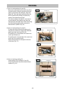
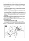
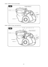
(3) When replacing or reassembling the Liner [54],
ensure that it is positioned and assembled as
illustrated in Fig. 46. In addition, coat 10 grams
of Hitachi Motor Grease on the liner sliding
portion of the Turn Table [13].
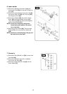
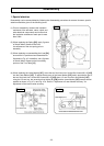
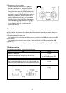
(4) When replacing the Laser Marker [107], screw the two Seal Lock Hex. Socket Set Screws M5 x 6 [103]
into the Laser Marker [107]. To adjust the accuracy of the Laser Marker [107] easily, protrude the tips of
the two Seal Lock Hex. Socket Set Screws M5 x 6 [103] about 1.5 mm from the Laser Marker [107]
using the 2.5-mm hex. bar wrench so that Holder (B) [106] and the Laser Marker [107] become almost
parallel as shown in Fig. 47-a and Fig. 47-b. Refer to "Adjustment of Laser Marker Accuracy" for
adjustment of the laser marker accuracy.
Reassembl
y
Fig. 47-a Fig. 47-b
Fig. 46