


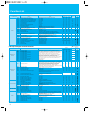
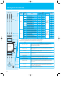

Function List
9
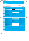
C Group: Intelligent terminal functions
: Allowed
[
X
: Not allowed
]
Note: C014: 01 for UL version.
Run mode
edit
Function Code Name Range
Default
-EF(CE)
-U(UL) -R(JP)
Unit
Lo
Intelligent input
terminal
C001
C201
C002
C202
C003
C203
C004
C204
C005
C205
Terminal [1] function
Terminal [1] function, 2nd motor
Terminal [2] function
Terminal [2] function, 2nd motor
Terminal [3] function
Terminal [3] function, 2nd motor
Terminal [4] function
Terminal [4] function, 2nd motor
Terminal [5] function
Terminal [5] function, 2nd motor
00(FW:Forward), 01(RV:Reverse), 02-05(CF1-CF4:Multispeed command),
06(JG:Jogging), 07(DB:External DC braking), 08(SET:Second motor constants
setting), 09(2CH:Second accel./decel.), 11(FRS:Free-run stop), 12(EXT:External trip),
13(USP:Unattended start protection), 15(SFT:Software lock), 16(AT:Analog input
selection), 18(RS:Reset), 19(PTC:Thermistor input), 20(STA:3-wire start),
21(STP:3-wire stop), 22(F/R:3-wire fwd./rev.), 23(PID:PID On/Off), 24(PIDC:PID
reset), 27(UP:Remote-controlled accel.), 28(DWN:Remote-controlled decel.),
29(UDC:Remote-controlled data clearing), 31(OPE:Operator control),
50(ADD: Frequency setpoint), 51(F-TM: Force terminal enable), 52(RDY: Quick Start
Enable), 53(S-ST: Special-Set (select) 2nd Motor Data), 64(EMR:Safety stop),
255(NO:Not selected)
00
00
01
01
02
02
03
03
18
18
00
00
01
01
16
16
13
13
18
18
-
-
-
-
-
X
X
X
X
X
X
X
X
X
X
X
X
X
X
X
X
X
X
X
X
Hi
C011-
C015
Terminal [1] to [5] active state
00(NO)/01(NC) 00 00*
-
XX
C021
Terminal [11] function
00(RUN:run signal), 01(FA1:Frequency arrival type 1 - constant speed),
02(FA2:Frequency arrival type 2 - over-frequency), 03(OL:overload
advance notice signal), 04(OD:Output deviation for PID control),
05(AL:alarm signal), 06(DC:Wire brake detect on analog input),
07(FBV: Feedback voltage comparison), 08(NDc: Network
Disconnection), 09(LOG: Logic operation result), 10(ODC: Option Card
Detection Signal), 43(LOC:Low load detection)
01 01
-
XX
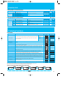
Intelligent input
terminal
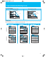
C026
C028
C031
C036
C038
C039
C041
C241
C042
C043
C044
C052
C053
Alarm relay function
[AM] signal selection
Terminal [11] active state
Alarm relay active state
Output mode of low load detection signal
Low load detection level
Overload level setting
Overload level setting, 2nd motor
Frequency arrival setting for acceleration
Frequency arrival setting for deceleration
PID deviation level setting
Feedback comparison upper level
Feedback comparison lower level
05
00
00
01
01
0.0
0.0
3.0
100
0.0
05
00
00
01
01
0.0
0.0
3.0
100
0.0
-
-
-
-
-
A
Hz
Hz
%
%
%
00(Output frequency)/01(Output current)
00(NO)/01(NC)
00(NO)/01(NC)
00(Disabled)/01(During acceleration, deceleration and constant
speed)/02(During constant speed only)
0.0 to 2.0*Rated current
0.0*Rated current to 2.0*Rated current
0.0 to 400.0
0.0 to 400.0
0.0 to 100.0
0.0 to 100.0
0.0 to 100.0
X
X
X
X
X
X
X
X
X
X
X
X
X
X
X
X
Serial communication
C070
C071
C072
C074
C075
C076
C077
C078
SELECTION OF OPE/MODBUS
Communication speed selection
Node allocation
Communication parity selection
Communication stop bit selection
Communication error mode
Communication error time
Communication wait time
02(OPE or option)/03(485)
04(4800bps)/05(9600bps)/06(19200bps)
1. to 32.
00(No parity)/01(Even parity)/02(Odd parity)
1(1-bit)/2(2-bit)
00(Trip)/01(Trip after deceleration stop)/02(Disable)/
03(FRS)/04(Deceleration stop)
0.00 to 99.99
0. to 1000.
02
06
1.
00
1
02
0.00
0.
02
04
1.
00
1
02
0.00
0.
-
-
-
-
bit
-
sec
msec
X
X
X
X
X
X
X
X
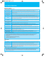
Analog meter setting
C081
C082
C086
0. to 200.
0. to 200.
0.0 to 10.0
[O] input span calibration
[OI] input span calibration
[AM] terminal offset tuning
100.
100.
0.0
100.
100.
0.0
%
%
V
00 (must not be changed)
00(Clear last frequency)/01(Keep last frequency adjusted by UP/DWN)
00(Cancel trip state at input signal ON transition)/ 01(Cancel trip state
at signal OFF transition)/
02(Cancel trip state at input signal ON transition)
00(RUN)/01(FA1)/02(FA2)/03(OL)/04(OD)
05(AL)/06(Dc)/07(FBV)/08(NDc)/10(ODc)/43(LOC)
00(AND)/01(OR)/02(XOR)
0.0 to 100.0
0.0 to 100.0
0.0 to 100.0
0.0 to 100.0
Others
C091
C101
C102
C141
C142
C143
C144
C145
C148
C149
Reserved (for factory adjustment)
Up/Down memory mode selection
Reset mode selection
Input A select for logic output 1
Input A select for logic output 2
Logic function select
ON delay time, output terminal 11
OFF delay time, output terminal 11
ON delay time, relay
OFF delay time, relay
00
00
00
00
01
00
0.0
0.0
0.0
0.0
00
00
00
00
01
00
0.0
0.0
0.0
0.0
00
00
01
01
02
02
03
03
18
18
00
01
05
00
00
01
01
0.0
0.0
3.0
100
0.0
02
04
1.
00
1
02
0.00
0.
100.
100.
0.0
00
00
00
00
01
00
0.0
0.0
0.0
0.0
-
-
-
-
-
-
sec
sec
sec
sec
X
X
X
X
X
X
X
X
X
X
X
X
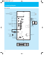
Run mode
edit
Function Code Name Range
Default
-EF(CE)
-U(UL)
-R(JP)
Unit
Lo Hi
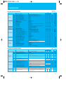
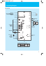
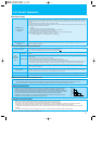
Others
b050
b051
b052
b053
b054
b055
b056
b080
b082
b083
b084
b085
b086
b087
b088
b089
b091
b092
b130
b131
b133
b134
b140
b150
b151
Selection of the non stop operation
Non stop operarion start voltage setting
OV-LAD Stop level of non stop operation setting
Deceleration time of non stop operation setting
Frequency width of quick deceleration setting
DC bus AVR P-gain
DC bus AVR I-time
[AM] terminal analog meter adjustment
Start frequency adjustment
Carrier frequency setting
Initialization mode (parameters or trip history)
Country code for initialization
Frequency scaling conversion factor
STOP key enable
Restart mode after FRS
Monitor display select for networked inverter
Stop mode selection
Cooling fan control (see note below)
Over-voltage LADSTOP enable
Over-voltage LADSTOP level
DC bus AVR selection
Threshold voltage of DC bus AVR setting
Over-current trip suppression
Carrier mode
Quick start enable
00(Disabled)/01(Enabled stop)/02(Enabled restart)
0.0 to 1000.0
0.0 to 1000.0
0.01 to 3000
0.0 to 10.0
0.2 to 5.0
0.0 to 150.0
0. to 255.
0.5 to 9.9
2.0 to 12.0
00(Trip history clear)/01(Parameter initialization)/
02(Trip history clear and parameter initialization)
00(JP)/01(CE)/02(US)
0.1 to 99.9
00(Enable)/01(Disable)
00(Restart from 0Hz)/01(Restart with frequency detection)
01(Output frequency)/02(Output current)/03(Rotation direction)/
04(PV, PID feedback)/05(Input terminal status)/
06(Output terminal status)/07(Scaled output frequency)
00(Deceleration and stop)/01(Free-run stop)
00(Always ON)/01(ON during RUN, OFF during STOP)/
02(Temperature controlled)
00(Disable)/01(Enable)
330 to 395V/660 to 790V
00(Disabled)/01(Enabled)
330 to 395V/660 to 790V
00(Disable)/01(Enable)
00(Disable)/01(Enable)
00(Disable)/01(Enable)
00
0.0
0.0
1.0
0.0
0.2
0.2
100.
0.5
3.0
00
01
1.0
00
00
01
00
00
00
380/760
00
380/760
01
00
00
00
0.0
0.0
1.0
0.0
0.2
0.2
100.
0.5
3.0
00
02
1.0
00
00
01
00
00
00
380/760
00
380/760
01
00
00
00
0.0
0.0
1.0
0.0
0.2
0.2
100.
0.5
3.0
00
00
1.0
00
00
01
00
00
00
380/760
00
380/760
01
00
00
-
V
V
sec
Hz
-
sec
-
Hz
kHz
-
-
-
-
-
-
-
-
-
V
-
V
-
-
-
X
X
X
X
X
X
X
X
X
X
X
X
X
X
X
X
X
X
X
X
X
X
X
X
X
X
X
X
X
X
X
X
Rated current