


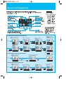
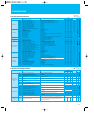
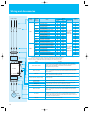

1-/3-phase 200V class
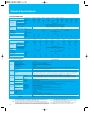
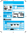
Standard Specifications
3
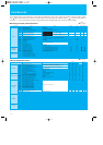
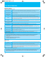
General Specifications
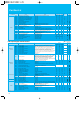
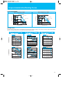
3-phase 400V class
002SFEF2
002NFU2
002LFRF2
0.2(1/4)
0.5
0.5
1.4
004SFEF2
004NFU2
004LFRF2
0.4(1/2)
1.0
1.0
2.6
005SFEF2
-
-
0.55(3/4)
1.1
1.2
3.0
007SFEF2
007NFU2
007LFRF2
0.75(1)
1.5
1.6
4.0
011SFEF2
-
-
1.1(1.5)
1.9
2.0
5.0
015SFEF2
015NFU2
015LFRF2
1.5 (2)
2.8
2.9
7.1
022
SFEF2
022NFU2
022LFRF2
2.2(3)
3.9
4.1
10.0
-
037LFU2
037LFRF2
3.7(5)
6.3
6.6
15.9
-
55LFU2
055LFRF2
5.5(7.5)
9.6
9.9
24.0
-
075LFU2
075LFRF2
7.5(10)
12.7
13.3
32.0
150% for 60 sec.
3-phase (3-wire) 200 to 240V (corresponding to input voltage)
SFEF: 1-phase 200 to 240V+10%, -15%, 50/60Hz
±5%
NFU: 1-/3-phase 200 to 240V+10%, -15%, 50/60Hz
±5%
LFU/LFRF: 3-phase 200 to 240V+10%, -15%, 50/60Hz
±5%
Self-cooling
Force ventilation
0.8
0.8
0.8
3.1
1.8
5.8
3.4
6.7
-
9.0
5.2
11.2
-
16.0
9.3
22.5
13.0
-
20.0
-
30.0
-
40.0
-SFEF2
-NFU2/LFU2
-LFRF2
1.0
0.9
0.9
1.5
-
-
1.5
1.5
1.1
2.4
-
-
2.4
2.3
2.2
2.5
2.4
2.4
-
2.3
2.4
-
4.2
4.2
-
4.2
4.2
Rated input voltage (V)
Rated input current
(A)
European Version
US Version
JP Version
Model X200-
Output Ratings
Input Rating
Enclosure *4
Cooling method
Applicable motor size, 4-pole kW(HP) *1
Rated capacity
Rated output current (A) *2
Overload capacity(output current)
Rated output voltage (V)
230V
240V
SFEF2
NFU2/LFUF2/LFRF2
Weight (kg)
Zero phase Reactor
-SFEF2
-NFU2/LFU2/LFRF2
-LFRF2
Integrated EMC filter
Model X200-
004HFEF2
004HFU2
004HFRF2
0.4(1/2)
1.0
1.2
1.5
007HFEF2
007HFU2
007HFRF2
0.75(1)
1.7
2.0
2.5
015HFEF2
015HFU2
015HFRF2
1.5 (2)
2.6
3.1
3.8
022HFEF2
022HFU2
022HFRF2
2.2(3)
3.8
4.5
5.5
030HFEF2
-
-
3(4)
5.4
6.4
7.8
040HFEF2
040HFU2
037HFRF2
4(5)
5.9
7.1
8.6
055HFEF2
055HFU2
055HFRF2
5.5(7.5)
9.0
10.8
13.0
075HFEF2
075HFU2
075HFRF2
7.5(10)
11.1
13.3
16.0
150% for 60 sec.
3-phase (3-wire) 380 to 480V (corresponding to input voltage)
3-phase 380 to 480V
+
10%, -15%, 50/60Hz
±
5%
IP20
Self-cooling Force ventilation
1.5
1.4
1.5
2.0 3.3 5.0 7.0 10.0 11.0 16.5 20.0
Output Ratings
Input Rating
Enclosure *4
Cooling method
Applicable motor size, 4-pole kW(HP) *1
Rated capacity
Rated output current (A) *2
Overload capacity(output current)
Rated output voltage (V)
European Version
US Version
JP Version
2.3
2.2
2.3
2.4
2.3
2.4
2.4
2.3
2.4
2.4
-
2.4
2.4
2.3
2.4
4.2
4.2
4.2
4.2
4.2
4.2
Rated input voltage (V)
Rated input current (A)
400V
480V
-HFEF2
-HFU2
-HFRF2
Weight (kg)
Zero phase Reactor
Integrated EMC filter
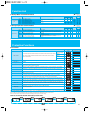
Item General Specifications
Line-to-line sine wave pulse-width modulation (PWM) control
0.5 to 400Hz
Digital command :±0.01%, Analog command±0.4% (25±10˚C)
Digital: 0.1Hz, Analog: (max frequency)/1000
V/f control,V/f variable (constant torque, reduced torque)
0.01 to 3000 sec. (linear, sigmoid), two-stage accel./decel.
100%/6Hz
2.0 to 12kHz
Over-current, over-voltage, under-voltage, overload, overheat, ground fault at power-on, input over-voltage, external trip, EEPROM error,
CPU error, USP error, Termister error, Driver error, Safety stop
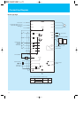
10kohm input impedance, sink/source logic selectable
FW(Forward), RV(Reverse), CF1-CF4(Multispeed command), JG(Jogging), DB(External DC braking), SET(Second motor constants setting),
2CH(Second accel./decel.), FRS(Free-run stop), EXT(External trip), USP(Unattended start protection), SFT(Software lock), AT(Analog input
selection), RS(Reset), PTC(Thermistor input) *8, STA(3-wire start), STP(3-wire stop), F/R(3-wire fwd./rev.), PID(PID On/Off), PIDC(PID reset),
UP/DWN(Remote-controlled accel./decel.) , UDC(Remote-controlled data clearing), OPE(Operator control), ADD(ADD frequency enable), F-
TM(force terminal mode), RDY(quick start enable),S-ST(Special-Set 2nd Motor Data),EMR(Safety stop), NO(Not selected)
27V DC 50mA max open collector output, 1 terminals 1c output 250V AC/30V DC 2.5A relay (AL0, AL1, AL2 terminals)
RUN(run signal), FA1(Frequency arrival type 1 - constant speed), FA2(Frequency arrival type 2 - over-frequency), OL(overload advance
notice signal), OD(Output deviation for PID control), AL(alarm signal), DC(Wire brake detect on analog input), FBV(PID Second Stage
Output), NDC(ModBus Network Detection Signal), LOG(Logic Output Function), ODC(Option Card Detection Signal), LOC(Low load)
0 to 10V DC
Analog Frequency monitor, analog current monitor
4-digits 7 segment LEDs
Parameter setting, output frequency, output current, scaled value of output frequency, trip history, I/O terminal condition, output
voltage. Rotation direction, PID Feedback, RON time, Power-on time.
Power, Alarm, Run, Prg, Hz and A Potentiometer, RUN, STOP/RESET, UP, DOWN, FUN and STR keys
Up and Down keys / Value settings or analog setting via potentiometer on operator keypad
0 to 10 V DC, 4 to 20 mA
RS485 interface (Modbus RTU)
Run key / Stop key (change FW/RV by function command)
FW Run/Stop (NO contact), RV set by terminal assignment (NC/NO), 3-wire input available
RS485 interface (Modbus RTU)
-
10 to 50˚C(carrier derating required for aambient temperature higher than 40°C), no freezing
-
20 to 65˚C
20 to 90% RH
5.9mm/s
2
(0.6G) 10 to 55Hz
Altitude 1,000 m or less, indoors (no corrosive gasses or dust)
AVR (Automatic Voltage Regulation), V/f characteristic selection, accel./decel. curve selection, frequency upper/lower limit, 16 stage
multispeed, PID control, frequency jump, external frequency input bias start/end, jogging, cooling fan On/Off, trip history etc.
Remote operator with copy function (SRW-0EX), input/output reactors, DC reactors, radio noise filters, braking resistors, braking units, LCR filter, communication cables (ICS-1, 3)
Control
Input terminal
Output signal
Operator
Operation
Environment
Other functions
Coating color
Options
Control method
Output frequency range *5
Frequency accuracy *6
Frequency setting resolution
Voltage/Frequency Characteristic
Acceleration/deceleration time
Starting torque *7
Carrier frequency range
Protective functions
Specification
Functions
Intelligent output terminal
Analog output terminal
Display
Status LED Interface
Frequency setting
FW/RV Run
Operating temperature
Storage temperature
Humidity
Vibration
Location
Operator keypad
External signal
Serial port
Operator Keypad
External signal
Serial port
Function
Specification
Function
Specification
Function
Note 1:
The applicable motor refers to Hitachi standard 3-phase motor (4-pole). When using other motors, care must be
taken to prevent the rated motor current (50/60 Hz) from exceeding the rated output current of the inverter.
Note 2:
The output voltage decreases as the main supply voltage decreases (except when using the AVR function). In
any case, the output voltage cannot exceed the input power supply voltage.
Note 3: The braking torque via capacitive feedback is the average deceleration torque at the shortest
deceleration (stopping from 50/60 Hz as indicated). It is not continuous regenerative braking torque.
The average decel torque varies with motor loss. This value decreases when operating beyond 50 Hz.
If a large regenerative torque is required, the optional regenerative braking resistor should be used.
Note 4: The protection method conforms to JEM 1030.
Note 5: To operate the motor beyond 50/60 Hz, consult the motor manufacturer
for the maximum allowable rotation speed.
Note 6: The output frequency may exceed the maximum frequency setting
(A004 or A204) for automatic stabilization control.
Note 7: At the rated voltage when using a Hitachi standard 3-phase, 4pole
motor.
Note 8: Only terminal 5 is assignable the PTC (thermistor) function.
Blue
EN61800-3 category C1 filter
IP20
-
EN61800-3 category C2 filter
Built-in
Built-in
-
-HFEF2
-HFU2/HFRF2
-HFRF2
Specification