


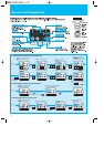
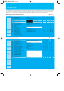
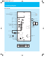
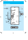
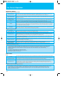

Connecting Diagram
11
AL2
AL1
AL0
R(L1)
T/N(L3)
S(L2)
(T1) U
(T3) W
(T2) V
P24
4
5
3
2
1
PCS
L
AM
H
O
OI
L
DC24V
DC10V
11
CM2
(+1)PD
(+)P
(
-
)N
DC link choke
Motor
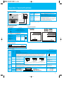
Intelligent relay
output contacts
Intelligent output
terminal
Current input
4mA
~
20mA
X200
Intelligent input
terminals
(5 terminals)
Source type
DC0
~
10V(8bit)
Terminal 1,2,3,4,5 H,O,OI 11
Common
Sink logic : L
LCM2
Source logic : PCS
Note 1: Common terminals are depend on logic.
Note 2: Please choose proper inverter input volotage rating.
10k
250
Frequency setting
1k
~
2k
Dynamic breaking umit (BRD)
P
P
N
RB
RB
R1
AL1
AL2
R2
Power source
1
-
/3
-
phase 200
~
240V+10%, -15%
3
-
phase 380
~
480V+10%, -15%
50/60Hz 5%
Short bar
Source type logic