


13
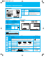
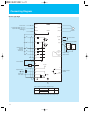
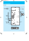
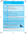
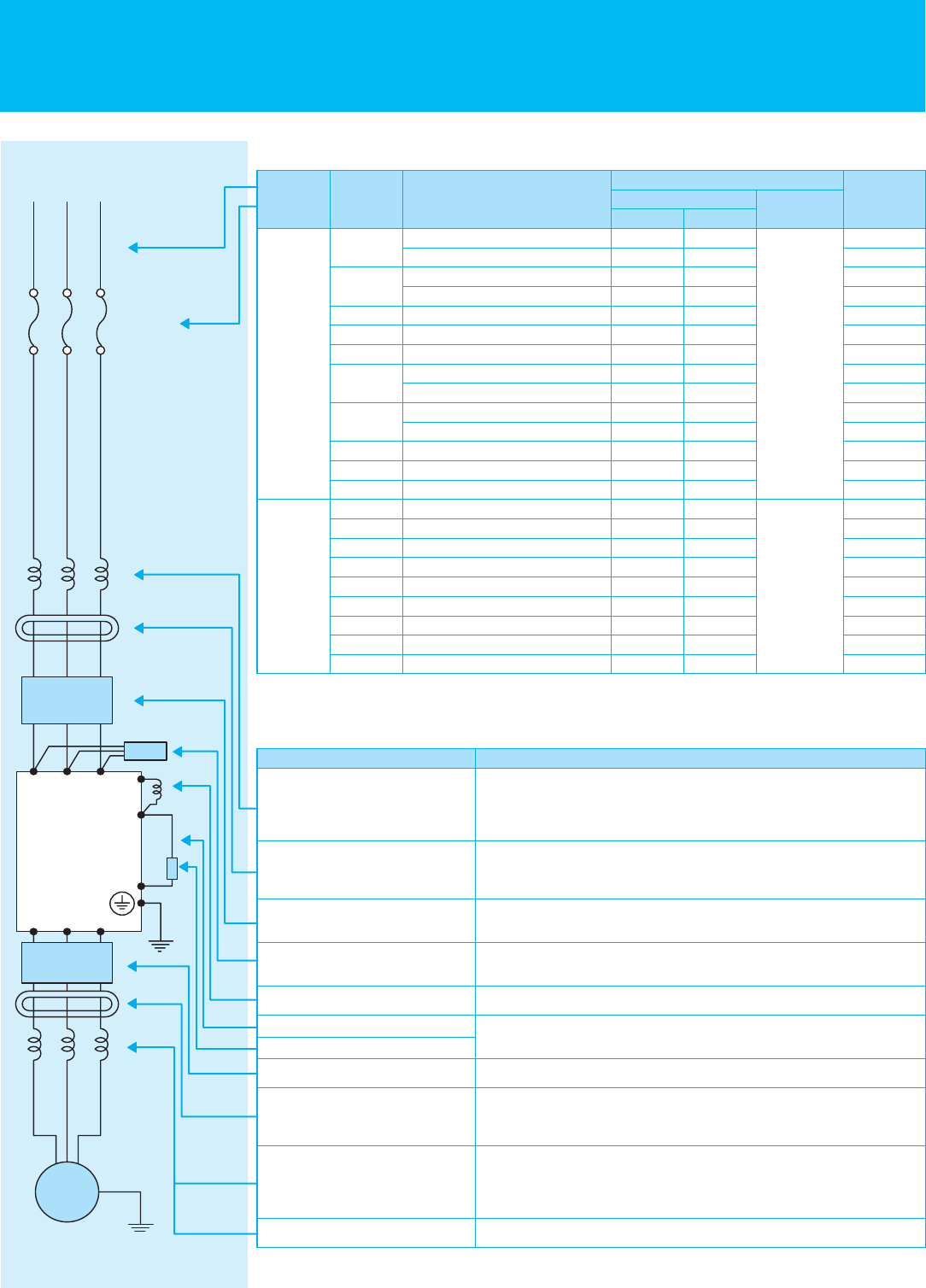
Wiring and Accessories
L1 L2 L3
U
(T1) V(T2) W(T3)
+1
+
-
IM
Power Supply
Fuse
Inverter
Motor
Note 1: Field wiring connection must be made by a UL and c-UL listed closed-loop terminal connector sized for the wire gauge involved.
Connector must be fixed using the crimping tool specified by the connector manufacturer.
Note 2: Be sure to use large wire gauges for power wiring if the distance exceeds 20m (66ft).
Note 3: Use 0.75mm
2
/18 AWG wire for the relay terminals (AL0, AL1 and AL2) signal wire.
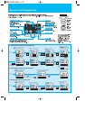
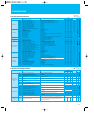
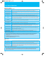
Name
Function
This is useful in suppressing harmonics induced on the power supplylines,
or when the main power voltage imbalance exceeds 3% (and power source
capacity is more than 500kVA), or to smooth out line fluctuations.
It also improves the power factor.
Electrical noise interference may occur on nearby equipment such as a radio
receiver. This magnetic choke filter helps reduce radiat-ed noise (can also be
used on output).
Reduces the conducted noise on the power supply wiring generated by the
inverter. Connect to the inverter input side.
This capacitor filter reduces radiated noise from the main power wires in the
inverter input side.
Suppresses harmonics generated by the inverter.
This is useful for increasing the inverter’s control torque for high duty-cycle
(on-off) applications, and improving the decelerating capability.
Reduces radiated noise from wiring in the inverter output side.
Electrical noise interference may occur on nearby equipment such as a radio
receiver. This magnetic choke filter helps reduce radiated noise (can also be
used on input).
This reactor reduces the vibration in the motor caused by the inver-ter’s switching
waveforms, by smoothing the waveforms to approximate commercial power
quality. It is also useful when wiring from the inverter to the motor is more than
10m in length, to reduce harmonics.
Sine wave shaping filter for the output side.
Input side AC reactor
Radio noise filter
EMC filter
Radio noise filter (Capacitor filter)
DC link choke
Braking resistor
Braking unit
Output side noise filter
Radio noise filter
AC reactor
LCR filter
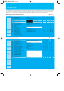
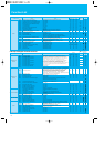
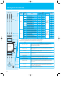
Input
Voltage
Applicable
Motor
(kW(HP))
Model
Wireing
Power Lines
AWG mm
2
Signal Lines
Fuse
(Class J)
0.2(1/4)
0.4(1/2)
0.55(3/4)
0.75(1)
1.1(1.5)
1.5(2)
2.2(3)
3.7(5)
5.5(7.5)
7.5(10)
0.4(1/2)
0.75(1)
1.5(2)
2.2(3)
3(4)
3.7(5)
4.0(5)
5.5(7.5)
7.5(10)
X200-002NFU2/SFEF2
X200-002LFRF2
X200-004NFU2/SFEF2
X200-004LFRF2
X200-005SFEF2
X200-007NFU2/SFEF2/LFRF2
X200-011SFEF2
X200-015NFU2/SFEF2
X200-015LFRF2
X200-022NFU2/SFEF2
X200-022LFRF2
X200-037LFU2/LFRF2
X200-055LFU2/LFRF2
X200-075LFU2/LFRF2
X200-004HFU2/HFEF2/HFRF2
X200-007HFU2/HFEF2/HFRF2
X200-015HFU2/HFEF2/HFRF2
X200-022HFU2/HFEF2/HFRF2
X200-030HFEF2
X200-037HFRF2
X200-040HFU2/HFEF2
X200-055HFU2/HFEF2/HFRF2
X200-075HFU2/HFEF2/HFRF2
14
16
14
16
14
14
10
10
14
10
14
12
10
8
16
16
16
14
14
14
14
12
12
2.0
1.25
2.0
1.25
2.0
2.0
5.5
5.5
2.0
5.5
2.0
3.5
5.3
8.4
1.25
1.25
1.25
2.0
2.0
2.0
2.0
3.3
3.3
18 to 28 AWG
0.14 to
0.75mm
2
shelded wire
18 to 28 AWG
0.14 to
0.75mm
2
shelded wire
10
10
10
10
10
15
15
20
20
30
30
30
40
50
3
6
10
10
15
15
15
20
25
400V
200V