


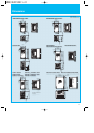
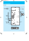

RS-485 communication/
operator selection switch
Safety stop ON/Off switch
SW7
SW8
ON
OFF
485
OPE
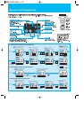
Operation / Terminal Functions
6
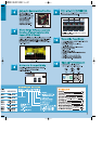
Hardware switches
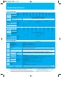
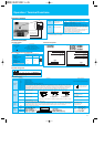
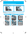
Terminal Description
Terminal Symbol
Screw Diameter and Terminal Width
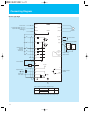
Terminal arrangement
Control circuit terminals
Terminal arrangement
Note 1:The standard keypad OPE (OPE-SRmini) can be used either the switch is set to 485 or OPE.
Note 2:Input terminal selection (EMR) cannot be chosen from an operaator. If the slide switch SW8 is turned ON, it
divides automatically and is attached.
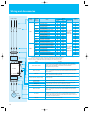
Terminal function
SW7
SW8
RS-485
communication/key pad
selection switch
Safety stop ON/OFF
Switch symbol Switch Name Switch Name Description
Select communication connector distination. *1
485
OPE [default]
RS-485 communicaiton via Modbus protocol
Keypad (option)
Select frequency and run command input source.
The SW8 is for the Safety signal input. If you turn this DIP switch
ON, the inverter is ready to receive Safety signal from the dedicated
terminal #3. Inverter shuts off the output by means of pure hardware
when a signal is given to the terminal.
Each signals related to this Safety input must be in accordance with
the norm. Additionally, the logic input terminal assign will be
changed automatically if the SW8 is made ON.
L1,L2,N/L3
U/T1,V/T2,W/T3
+
1,
+
+
-
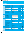
Main power supply input terminals
Inverter output terminals
DC reactor connection terminals
External braking unit connection terminals
Ground connection terminal
Terminal Symbol Terminal Name
Model
Screw diameter (mm)
002 - 004NFU2/SFEF2
002-007LFRF2
007- 022NFU2, 037LFU2
005 - 022SFEF2
015-037LFRF2
004- 040HFU2/HFEF2
004-037HFRF2
055- 075LFU2/LFRF2/HFU2/HFEF2/HFRF2
M3.5
M4
M5
Terminal width W (mm)
7.1
9.2
12
-
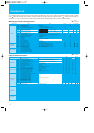
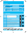
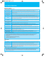
Terminal name
Description Ranges and Notes
Input/monitor
signals
AM
L
P24
PCS
5
4
3
2
1
Freqency
setting
Output
signals
11
CM2
Relay
output
AL2
AL1
AL0
H
O
OI
L
+10V analog reference
Analog input, voltage
Analog input, current
Common for inputs
Intelligent (programable) output terminals, selection from:
RUN(run signal), FA1(Frequency arrival type 1 -constant speed), FA2(Frequency arrival type 2 -over-frequency), OL(overload advance notice
signal), OD(Output deviation for PID control), AL(alarm signal), DC(Wire brake detect on analog input), FBV(Feedback voltage comparison),
NDc(Network Disconnection), LOG(Logic operation result), ODC(Option Card Detection signal), LOC(Low Load Detection).
Open collector output
L level at operation (ON)
27V DC, 50mA max.
Common for intelligent output terminals
10V DC, 10mA max
0 to 10V DC,
input impedance10kohm
4 to 20mA DC,
input impedance 250ohm
-
Voltage analog output
Common for inputs
+24V for logic inputs
Intelligent input common
0 to10V DC, 1mA max.
-
24V DC, 30mA (do not short to terminal L)
-
Intelligent (programable) input terminals, selection from:
FW(Forward), RV(Reverse), CF1-CF4(Multispeed command), JG(Jogging), DB(External DC braking), SET(Second motor constants setting),
2CH(Second accel./decel.), FRS(Free-run stop), EXT(External trip), USP(Unattended start protection), SFT(Software lock), AT(Analog input
selection), RS(Reset), PTC(Thermistor input), STA(3-wire start), STP(3-wire stop), F/R(3-wire fwd./rev.), PID(PID On/Off), PIDC(PID reset),
UP/DWN(Remote-controlled accel./decel.), UDC(Remote-controlled data clearing), OPE(Operator control), ADD(Frequency setpoint), F-
TM(Force terminal enable), RDY(Quick start enable), S-ST(Special-Set 2nd Motor Data), EMR(Safety stop) or NO(Not selected).
-
SW
P24
1
-
5
Operated by closing switch.
(Input logic is selectable)
+
-
+
-
Assign [AT] for input terminal to selecting frequency source from voltage or current.
(1kΩ
-
2kΩ)
DC0
-
10V
Input inpedance 10kΩ
DC4
-
20mA
Input inpedance 250Ω
VR
HOOIL HOOIL HOOIL
AC250V 2.5A (Resistive load)
0.2A (cos =0.4)
DC30V 3.0A (Resistive load)
0.7A (cos =0.4)
(minimum) AC100V 10mA
DC 5V 100mA