


OM-356 Page 36
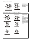
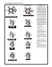
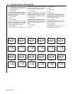
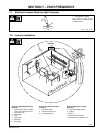
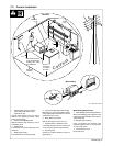
5-4. Voltmeter/Ammeter Help Displays
. All directions are in reference to the front
of the unit. All circuitry referred to is lo-
cated inside the unit.
0 Help 0 Display
Indicates a short in the thermal protection cir-
cuitry located on the transformer of the unit.
If this display is shown, contact a Factory Au-
thorized Service Agent.
1 Help 1 Display
Not used.
2 Help 2 Display
Indicates a malfunction in the thermal
protection circuitry located on the transform-
er of the unit. If this display is shown, contact
a Factory Authorized Service Agent.
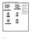
3 Help 3 Display
Indicates the transformer of the unit has
overheated. The unit has shut down to allow
the fan to cool it (see Section 3-4). Operation
will continue when the unit has cooled.
4 Help 4 Display
Indicates a malfunction in the thermal
protection circuitry located on the rectifier
assembly of the unit. If this display is shown,
contact a Factory Authorized Service Agent.
5 Help 5 Display
Indicates the rectifier assembly of the unit
has overheated. The unit has shut down to
allow the fan to cool it (see Section 3-4). Op-
eration will continue when the unit has
cooled.
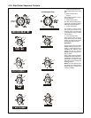
6 Help 6 Display
Not used.
7 Help 7 Display
Not used.
8 Help 8 Display
Not used.
9 Help 9 Display
Indicates a short in the thermal protection cir-
cuitry located on the rectifier assembly of the
unit. If this display is shown, contact a Facto-
ry Authorized Service Agent.
10 Help 10 Display
Indicates Remote Output control is acti-
vated. Release Remote Output control to
clear help message.
11 Help 11 Display
Indicates Output Selector switch is not in
correct position (see Section 4-2).
A
V
A
V
3
A
V
HLP
––1
HLP
––2
HLP
––3
A
V
HLP
––4
A
V
HLP
––5
A
V
HLP
––6
A
V
HLP
––7
A
V
HLP
––8
6
8
2 5
7
1 4
A
V
HLP
––9
9
A
V
HLP
–10
10
A
V
HLP
–11
11
A
V
HLP
––0
0