


. A complete Parts List is available at www.MillerWelds.com
OM-244 013 Page 13
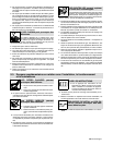
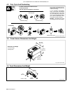
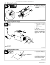
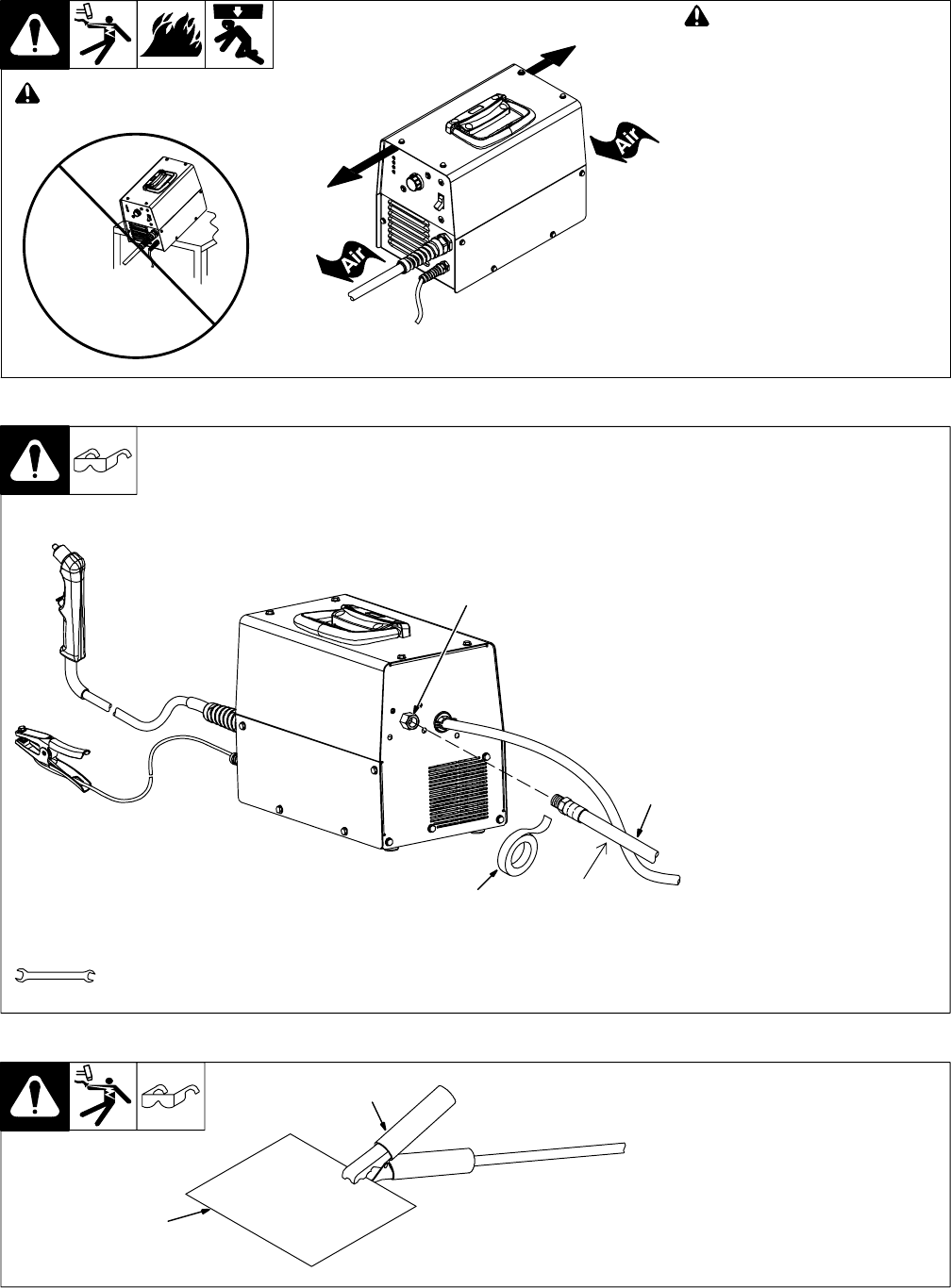
4-5. Selecting A Location
loc_2 3/96 - Ref. 244 405-A
! Do not move or operate unit
where it could tip.
18 in.
(460 mm)
18 in.
(460 mm)
! Special installation may be
required where gasoline or
volatile liquids are present ï
see NEC Article 511 or CEC
Section 20.
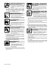
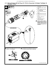
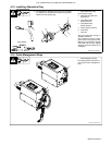
4-6. Connecting Gas/Air Supply
Ref. 244 423-A
. Use only clean, dry air with 90
to 120 psi (621 to 827 kPa)
pressure.
1 Gas/Air Inlet Opening
2 Hose
3 Teflon Tape
Obtain hose with 1/4 NPT right-
hand thread fitting. Wrap threads
with teflon tape (optional) or apply
pipe sealant, and install fitting in
opening. Route hose to gas/air
supply.
Tools Needed:
3
From Gas/Air
Supply
1
2
9/16 in.
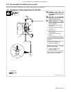
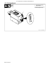
4-7. Connecting Work Clamp
. Do not connect work clamp to
the portion of the workpiece
that will fall when cut.
1 Work Clamp
2 Workpiece
Connect work clamp to a clean,
paint-free location on workpiece, as
close to cutting area as possible.
1
2
Ref 803 915-A