


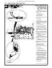
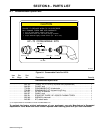
. A complete Parts List is available at www.MillerWelds.com
OM-244 013 Page 28
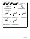
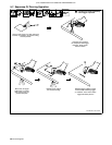
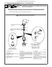
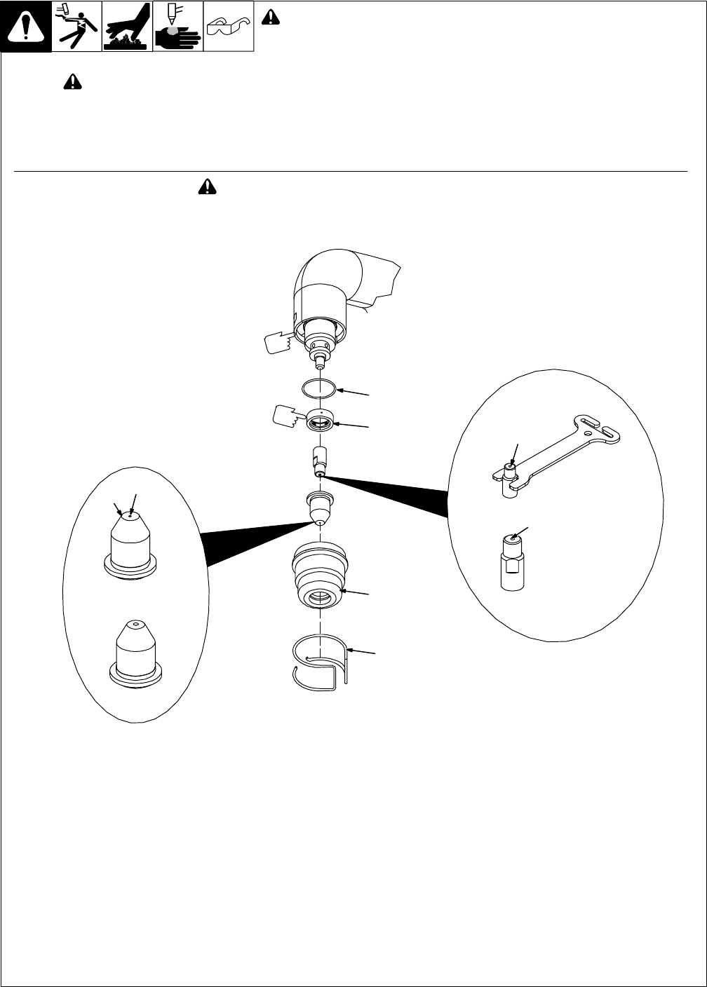
6-5. Checking/Replacing Retaining Cup, Tip, And Electrode
. A good practice is to replace both the tip and electrode at the same time.
Ref. 804 851-A
Turn Off power source.
1 Shield Cup
Remove shield cup. Check cup for cracks,
and replace if necessary.
2 O-Ring
Check O-ring for cracks or worn spots and
replace, if necessary.
3 Tip
4 Opening
Remove tip. Check tip, and replace if open-
ing is deformed or 50% oversize. If inside of
tip is not clean and bright, clean with steel
wool. Be sure to remove any pieces of steel
wool afterwards.
5 Electrode
Check electrode. If center has a pit more
than a 1/16 in. (2 mm) deep, remove and re-
place electrode.
6 Swirl Ring
Remove swirl ring. Check ring, and replace
if side holes are plugged.
Carefully reassemble parts in reverse order.
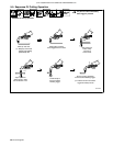
7 Stand-off Guide
Placing the stand-off guide on the end of
the torch provides an optional method of
maintaining a 1/16 in. (1.6 mm) gap
between tip and workpiece.
Make sure this area is clean of
any debris.
Make sure swirl ring is clean of any
debris and no holes are
obstructed.
New
Worn
*1/32 in. (1 mm) — 1/16 in. (2 mm)
maximum pit depth depending on
acceptable cut quality.
4
3
6
1
Replace tip if opening is
deformed or 50% oversized.
2
. Lightly tighten electrode
using electrode wrench
(15-20 in.lb (1.7-2.3 NVm).
7
! Turn Off power source before checking torch parts.
! Overtightening will strip threads. Do not overtighten retaining cup during
assembly. Do not cross-thread parts causing stripping. Use care during torch
assembly and parts replacement.
! Inspect shield cup, tip, and electrode for wear before cutting or whenever cutting speed has been significantly
reduced. Do not operate torch without a tip or electrode in place. Be sure to use genuine replacement parts.
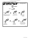
New
Worn
5
*Pit
Depth
Electrode
Wrench