


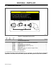
. A complete Parts List is available at www.MillerWelds.com
OM-244 013 Page 29
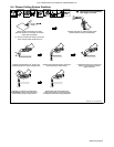
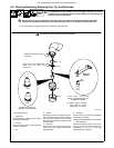
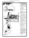
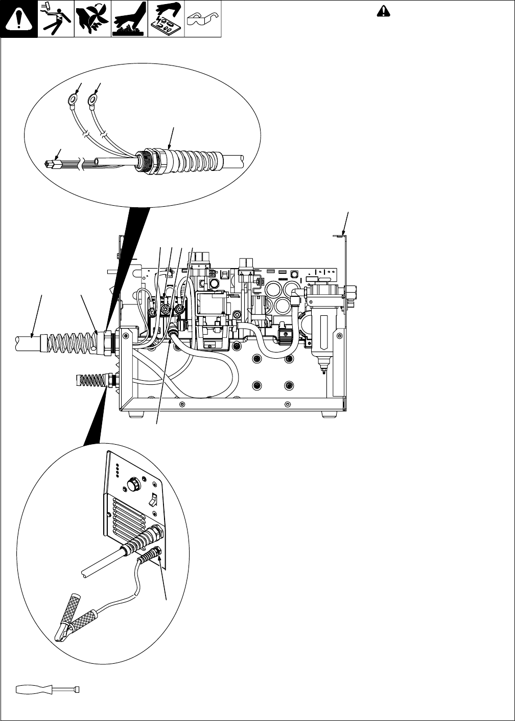
6-6. Torch And Work Cable Connections
! Turn power Off, and
disconnect input power plug
from receptacle. Check to
see that all diagnostic LED’s
have stopped flashing
before removing wrapper
from unit.
If torch or work cable needs to be
removed or replaced, proceed as
follows:
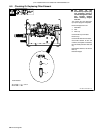
1 Power Source
Remove wrapper from unit.
Torch Connections
Remove existing torch cable from
unit.
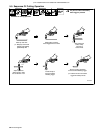
2 Strain Relief
3 Torch Cable
Insert strain relief on end of cable
through front panel opening. Slide
strain relief nut onto torch cable, but
do not tighten.
4 Air Line Connector
Insert air line into solenoid fitting.
5 Plug PLG4/Receptacle RC4
Connect PLG4 from torch to
receptacle RC4 on end of wiring
harness connected to circuit board
PC1.
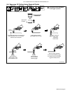
Route torch white and red leads
and work black lead through
sleeving the same way as the unit
was originally.
6 Ring Terminal And TORCH
WHITE Terminal
Connect ring terminal on end of
torch white lead to TORCH WHITE
terminal.
7 Ring Terminal And TORCH
RED Terminal
Connect ring terminal on end of
torch red lead to TORCH RED
terminal.
Tighten strain relief screw.
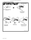
Work Cable Connections
Remove existing work cable from
unit.
8 Strain Relief
Loosen strain relief screw.
. Be sure to allow some work
cable slack inside the unit.
Insert strain relief on end of cable
through front panel opening. Slide
strain relief nut onto work cable and
secure strain relief to front panel.
9 Work Lead Ring Terminal And
WORK BLACK Terminal
Connect ring terminal on end of
work clamp lead to terminal labeled
WORK BLACK. Route lead along
torch lead bundle.
Reinstall wrapper.
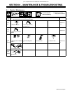
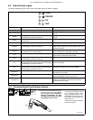
Tools Needed:
Ref. 804 887-A / 244 409-A / Ref. 244 405-A
3/8 in.
1
2
5
6 7
8
2
7 9
3
4
5 6