


. A complete Parts List is available at www.MillerWelds.com
OM-244 013 Page 15
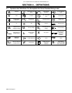
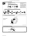
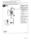
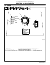
4-10. Serial Number And Rating Label Location
The serial number and rating information for this product is located on the back. Use rating label to determine input power requirements and/or rated
output. For future reference, write serial number in space provided on back cover of this manual.
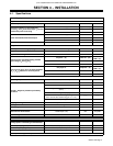
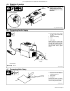
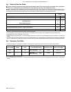
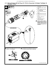
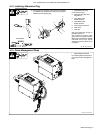
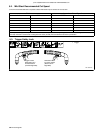
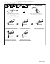
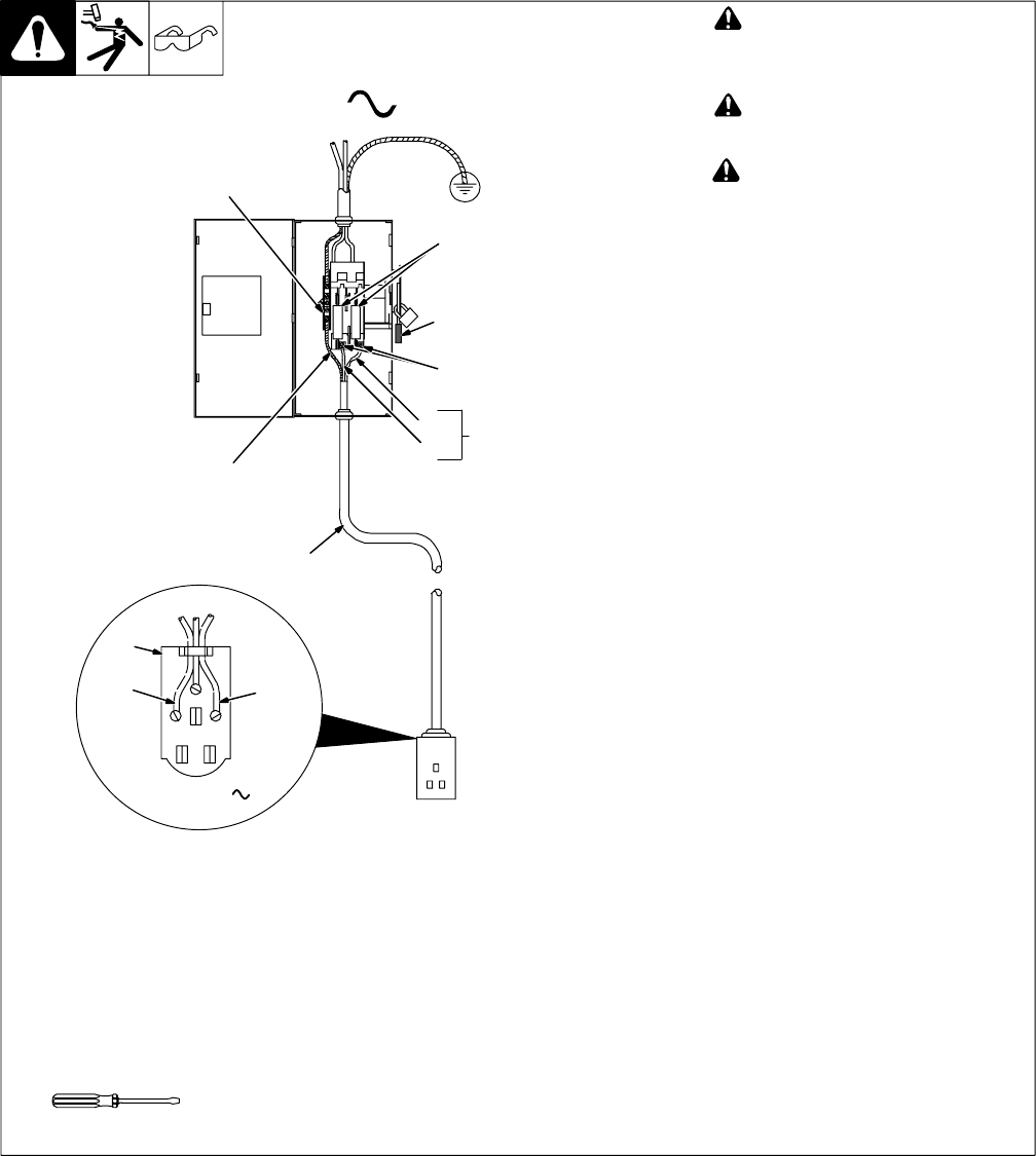
4-11. Connecting 1-Phase Input Power For 240 VAC
803 766-B / Ref. 802 443-A
! Installation must meet all
National and Local Codes ï have
only qualified persons make this
installation.
! Disconnect and lockout/tagout
input power before connecting
input conductors from unit.
! Always connect green or green/
yellow conductor to supply
grounding terminal first, and never
to a line terminal.
1 Black And White Input Conductor
(L1 And L2)
2 Green Or Green/Yellow Grounding
Conductor
3 Input Power Cord.
4 Disconnect Device (switch shown in
the OFF position)
5 Disconnect Device Grounding
Terminal
6 Disconnect Device Line Terminals
Connect green or green/yellow grounding
conductor to disconnect device grounding
terminal first.
Connect input conductors L1 and L2 to
disconnect device line terminals.
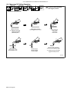
7 Over-Current Protection
Select type and size of over-current
protection using Section 4-8 (fused
disconnect switch shown).
8 Receptacle (NEMA 6-50R)
Customer Supplied
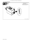
Close and secure door on disconnect
device. Remove lockout/tagout device,
and place switch in the On position.
4
3
L1
L2
1
=GND/PE Earth Ground
2
1
5
6
7
Tools Needed:
L1
L2
240 VAC, 1
8