


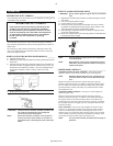

CONDENSATE DISCHARGE PIPING. If installing a condensate
discharge line, the piping must be at least one size larger than the
connection, as short and direct as possible, secured tightly and
routed to a suitable drain point or waste container. Condensate
must be disposed of in accordance with local, state, and federal
laws and regulations.
•
WARNING If an aftercooler, check valve, block valve, or any
other restriction is added to the compressor
discharge, install a properly-sized ASME approved
safety/relief valve between the compressor
discharge and the restriction.
INSTALLING ELECTRICAL WIRING (ELECTRIC MOTOR
UNITS) _____________________________________________
•
WARNING Electrical installation and service should be
performed by a qualified electrician who is familiar
with all applicable local, state and federal laws and
regulations.
GENERAL. The motor rating, as shown on the motor nameplate,
and the power supply must have compatible voltage, phase and
hertz characteristics.
WIRE SIZE. The electrical wiring between the power supply and
electric motor varies according to motor horsepower and other
factors. Install adequately sized power leads to protect against
excessive voltage drop during start-up. Refer to the National
Electric Code (NEC) for information on selecting the proper wire
size and securing electrical connections. If you connect additional
electrical equipment to the same circuit, consider the total electrical
load when selecting the proper wire size. DO NOT USE
UNDERSIZE WIRE.
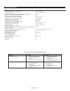
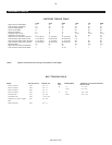
If wire size information is not available, the wire sizes shown in the
following wire selection chart can be used as a safe guide, if the
distance does not exceed 50 feet (15.3 m). For longer distances,
consult and electrical contractor or the local electric company for
recommendations.
MOTOR
HP
SINGLE
PHASE
THREE
PHASE
115V 230V 200V 230V 460V 575V
1 121414141414
1.5 10 14 14 14 14 14
2 8 14 14 14 14 14
3 8 12 14 14 14 14
5 4 8 10121414
7.5 6 8 10 14 14
10 8 8 12 14
15 4 6 10 10
20 3 4 8 10
25 1268
30 0168
MAGNETIC STARTER. If the motor installed on your unit has a
motor reset button, it does not require a magnetic starter. If the
motor does not have this button and the unit does not have a
factory-installed starter, install a magnetic starter with thermal
overload protection. Follow the manufacturer’s instructions for
installation. Ingersoll-Rand cannot accept responsibility for
damages arising from failure to provide adequate motor protection.
FUSES. Refer to the NEC to determine the proper fuse or circuit
breaker rating required. When selecting fuses, remember the
momentary starting current of an electric motor is greater than its
full load current. Time-delay or “slow-blow” fuses are recommended.
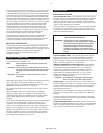
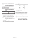
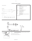
PRESSURE SWITCH. On units without a factory-installed pressure
switch, wire a pressure switch in accordance with the appropriate
wiring schematic in the DIAGRAMS section of this manual. Mount
the pressure switch in accordance with the manufacturer’s
recommendations. The connecting line to the receiver tank must be
as short and direct as possible, and certified safe for at least the
maximum working pressure of the unit.
CONNECTING A BATTERY (GASOLINE ENGINE UNITS) __
NOTE If you will be making connections to a remote
battery, the engine on the compressor unit must be
equipped with an alternator.
BATTERY. A 12 volt battery with a minimum current rating of 250
CCA (cold cranking amps) and minimum ampere-hour rating of 24
Ah should be sufficient for cranking most electric start engines.
BATTERY CABLES. Refer to the following table for size and length
recommendations.
Cable
Size (GA)
Maximum
Length
6 5’ (1.5 m.)
4 7’-2.5" (2.1 m.)
2 12’ (3.6 m.)
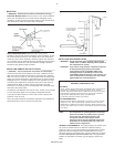
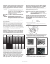
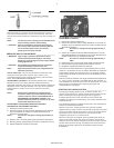
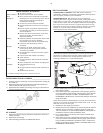
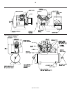
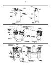
CONNECTION PROCEDURES:
1. Connect the battery positive (+) cable (A) to the starter solenoid
terminal (B).
2. Connect the battery negative (-) cable (C) to the bolt shown in the
following illustration. Secure the wire in place by screwing a
suitably-sized nut onto the bolt and down onto the terminal.
Kohler Honda
Kawasaki Ingersoll-Rand
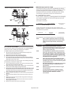
3. Connect the battery positive (+) cable (A) to the battery positive (+)
terminal.
4. Connect the battery negative (-) cable to the battery negative (-)
terminal.
5. Coat the terminals and cable ends with corrosion-preventive grease.
4
http://air.irco.com