


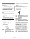
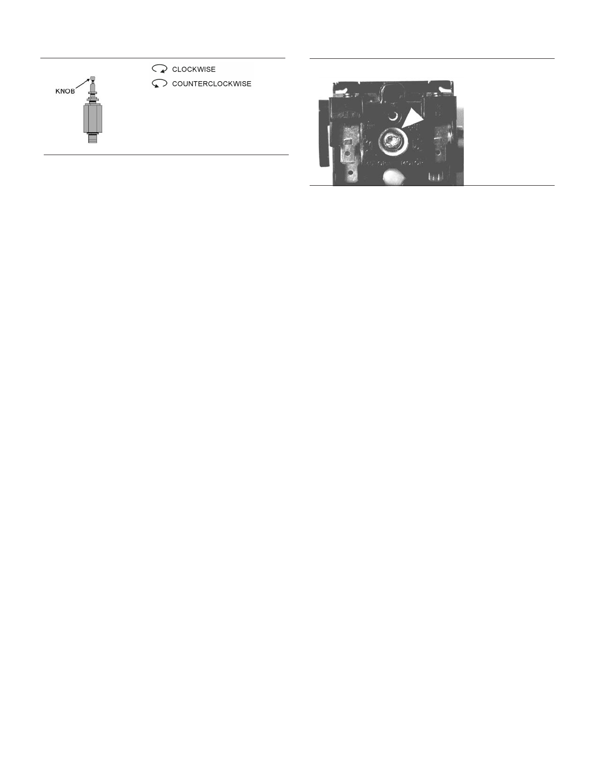
Auxiliary Valve.
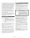
Select constant speed control if the unit restarts in less than 10
minute intervals or runs more than 40 minutes per hour. Turn the
knob fully counterclockwise to run the unit continually. When the
receiver tank pressure reaches 170 PSIG, the unit runs but does not
pump.
NOTE The auxiliary valve is factory pre-set at 5 PSIG lower
than the factory pressure switch setting.
•
CAUTION Running unloaded for more than 20 minutes per
hour or more than 15 minutes continually with the
use of constant speed control will cause oil
pumping and should be avoided.
PRESSURE SWITCH ADJUSTMENT ____________________
•
WARNING High voltage is present at the pressure switch
contacts when the power supply is connected.
Disconnect, lock and tag main power supply before
making adjustments.
•CAUTION Do not adjust the pressure switch to exceed the
maximum discharge pressure of the unit.
NOTE Adjust the pressure switch only if adjustments are
absolutely necessary.
CUT-IN & CUT-OUT. The cut-out (compressor shut-down) is the
pressure at which the switch contacts open, and the cut-in
(compressor restart) is the pressure at which the switch contacts
close. See COMPRESSOR CONTROLS.
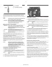
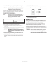
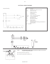
ADJUSTMENT CONTROLS. All pressure switches have a range
adjustment control (A). Some pressure switches also have a
differential adjustment (B) control. On switches without a differential
adjustment control, the span between cut-in and cut-out pressure
levels switches is factory set for 40 ± 4 PSIG and cannot be
adjusted.
NOTE Some pressure switches are equipped with an
on-off lever used to open and close the electrical
contacts inside the switch. THIS LEVER IS NOT A
DIFFERENTIAL ADJUSTMENT CONTROL. The
pressure switches with the on-off lever do not have
a differential adjustment control.
ADJUSTMENT PROCEDURES (SWITCHES WITHOUT
DIFFERENTIAL ADJUSTMENT CONTROL):
1. Remove the pressure switch cover.
2. Adjust the range by turning the range adjustment screw clockwise
(in) to increase the cut-out point or counter-clockwise (out) to
decrease the cut-out point.
NOTE: One full turn changes the setting approximately 2
PSIG.
3. Replace cover, reconnect power supply and start the compressor.
4. Note the pressure gauge reading at which the compressor cuts out.
5. Repeat adjustment procedure if necessary.
ADJUSTMENT PROCEDURES (SWITCHES WITH DIFFERENTIAL
ADJUSTMENT CONTROL):
1. Remove the pressure switch cover.
2. Set the cut-in pressure with the range adjustment nut. Turn the nut
clockwise (in) to increase the pressure or counter-clockwise (out) to
decrease the pressure.
NOTE: One full turn changes the setting approximately 2
PSIG.
3. Set the cut-out pressure with the differential adjustment. Turn the
differential adjustment nut clockwise (in) to increase the pressure or
counter-clockwise (out) to decrease the pressure.
NOTE: One full turn changes the setting approximately 2
PSIG.
4. Replace the cover, reconnect the power supply and start the unit.
5. Note the pressure gauge reading at which the unit cuts out.
6. Repeat the adjustment procedure if necessary.
The minimum possible differential is approximately 20% of cutout
pressure. It is advisable to have as wide a differential as possible to
avoid frequent starting and stopping of the unit. Note the pressure
gauge reading at which the unit cuts-out and re-establish this point
if necessary.
Note the interaction between the range and differential adjustments,
i.e., if the cut-out is increased, the differential will also increase, or
if the differential is narrowed, the cut-out will be reduced, etc. These
factors must be considered when adjusting the switch and
compensated for accordingly.
STARTING UNLOADING SYSTEM ______________________
The starting unloading feature exists on certain models. The
purpose of the system is to relieve cylinder pressure when the unit
stops, permitting it to start against a light load. A light load
increases the life of the driver and belts and also reduces the
possibility of tripping the overload relay. The system operates in the
following manner:
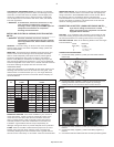
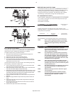
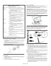
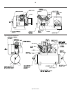
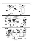
The centrifugal unloader is attached to the end of the crankshaft as
shown in the following illustrations.
When the unit starts, centrifugal force acts upon the unloader
weights and they swing outward. This permits the plunger and thrust
pin to move inward and the pilot valve to close. The escape path to
atmosphere for the cylinder pressure is now closed and the
compressor pumps air in a normal manner.
When the unit stops, the weights retract, permitting the thrust pin
spring to move the plunger and thrust pin outward. The thrust pin
opens the pilot valve and the trapped air pressure escapes from the
cylinder and intercooler through a passage in the frame end cover,
through the unloader tube and to atmosphere through the inlet
filter/silencer.
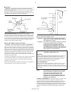
7
Pressure Switch Range Adjustment.
http://air.irco.com