


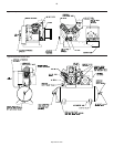
PILOT VALVE ADJUSTMENT __________________________
If the pilot valve tube line is excessively hot, it is a good indication
that the pilot valve is leaking and adjustment is required.
To adjust the pilot valve, proceed as follows:
1. Stop the unit and disconnect and tag the electrical supply main
switch to prevent accidental start-up.
2. Remove the pilot valve tube and the tube fittings.
3. Remove the pilot valve body and all existing shims.
4. Screw the pilot valve body back into the frame end cover (without
any shims) until contact with the thrust pin is felt. Advance the pilot
valve body 1/4 to 1/2 turn more.
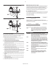
If contact with the thrust pin cannot be felt, the following steps may
be necessary to locate the contact point:
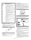
1. Insert a small instrument (punch, rod, nail, etc.) into the end of the
pilot valve until it contacts the valve stem.
2. While still inserted in the pilot valve, make a mark on the instrument
even with the outside edge of the pilot valve body.
3. Keeping the instrument pressed lightly against the valve stem, screw
the pilot valve body into the frame end cover. When the mark on the
instrument starts moving out away from the edge of the pilot valve
body, contact has been made with the thrust pin.
4. Advance the pilot valve body 1/4 to 1/2 turn more and proceed with
step five.
5. Measure the gap between the pilot valve body and the frame end
cover.
6. Remove the pilot valve body and add enough shims to fill the gap
measured in step five.
7. Screw the pilot valve body back into the frame end cover until the
body is tight on the shims.
8. Reconnect the pilot valve tube and tube fittings.
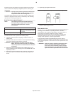
BREATHER/UNLOADER BY-PASS _____________________
The breather/unloader by-pass tube lines eliminates air pressure
build-up in the compressor frame by providing a passage for the air
to escape through the inlet unloader (if opened) or (if closed)
through the check valve, therefore, by-passing the inlet unloader
and escaping to atmosphere through the inlet filter/silencer.
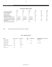
OIL CONSUMPTION CHECK___________________________
A rule of thumb in determining a "passing grade" for oil consumption
is to consider consumption at or above 50 horsepower-hours per
ounce to be acceptable.
The formula is as follows:
Horsepower X
Hours of Operation
= Horsepower Hours
per Ounce
Ounces of Oil Used
To apply this formula, consider the size of the machine. In the
following example, a 5 horsepower compressor uses 2 ounces of oil
every 20 hours of operation.
5 Horsepower X 20 Hours of
Operation
= 50 Horsepower
Hours per Ounce
2 Ounces of Oil Used
The compressor in the example passes the oil consumption test.
NOTE New or rebuilt compressor pumps will discharge
higher than normal amounts of oil until the piston
rings are seated (approximately 100 operating
hours).
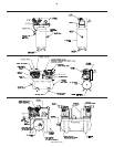
MAINTENANCE
•WARNING Before performing maintenance, release air
pressure from the system and disconnect, lock and
tag the main power supply or disconnect the wire
from the engine spark plug.
NOTE All compressed air systems contain maintenance
parts (e.g. lubricating oil, filters, separators) which
are periodically replaced. These used parts may be,
or may contain, substances that are regulated and
must be disposed of in accordance with local, state,
and federal laws and regulations.
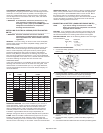
NOTE Take note of the positions and locations of parts
during disassembly to make reassembly easier. The
assembly sequences and parts illustrated may differ
for your particular unit.
NOTE Any service operations not explained in this manual
should be performed by an authorized service
representative.
NOTE Reference the engine owner's manual for engine
care information.
NOTE The following maintenance schedule has been
developed for typical applications. Maintenance
intervals should be shortened in harsher
environments.
8
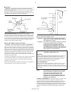
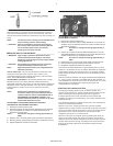
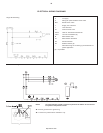
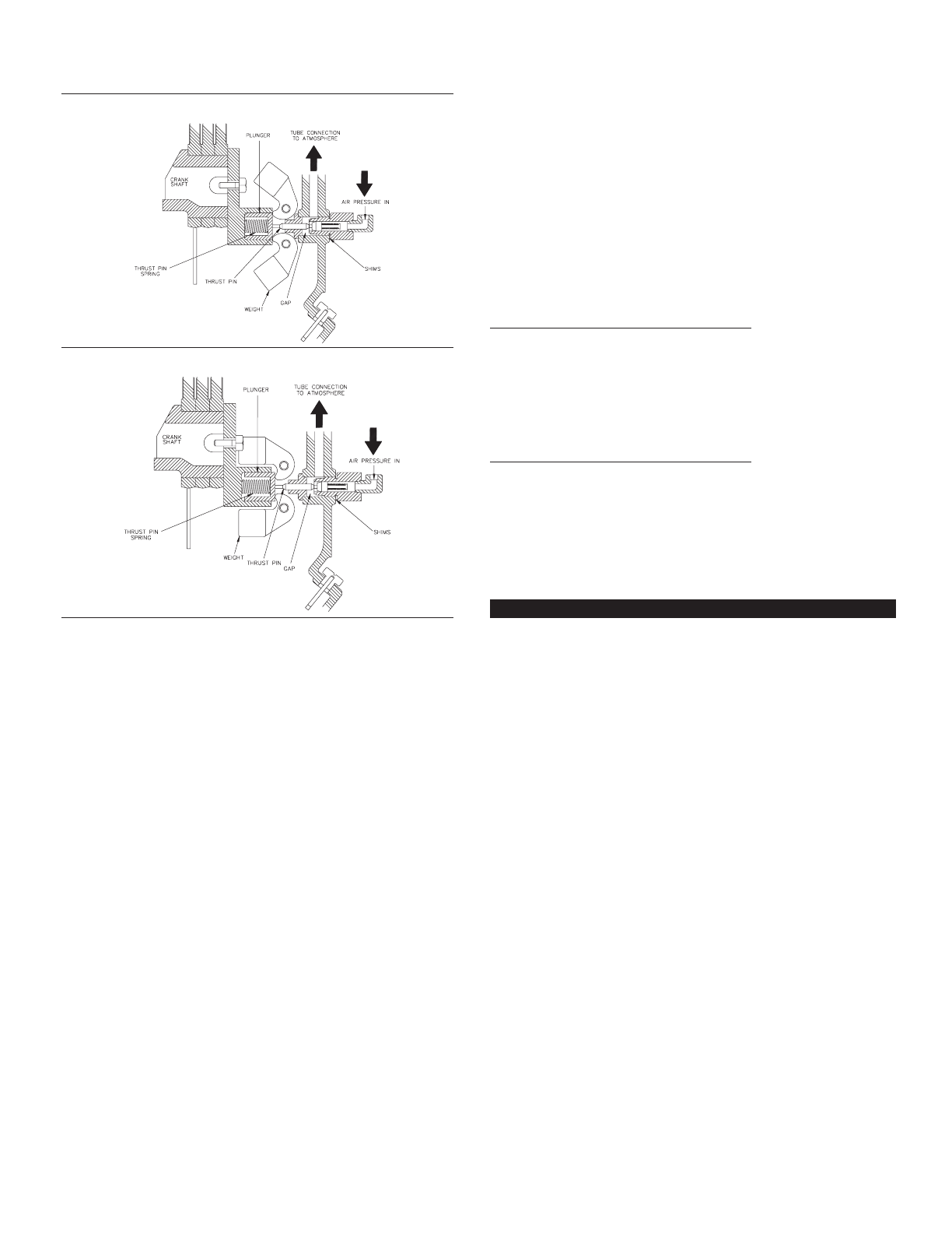
Position of weight and thrust pin when unit is operating.
Position of weight and thrust pin when unit is stopped.
http://air.irco.com