


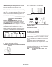
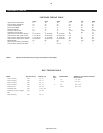

MAINTENANCE SCHEDULE
l
Check for oil leaks.
Daily or Before
Each
Operation
l
Check lubricant level. Fill as needed.
l
Drain receiver tank condensate (if automatic
draining device is not provided). Open manual
drain valve and collect and dispose of
condensate accordingly.
l
Check for unusual noise and vibration.
l
Ensure beltguards and covers are securely in
place.
l
Ensure engine (if supplied) is filled with fuel
and lubricant according to the manufacturer’s
recommendations.
l
Ensure area around compressor is free from
rags, tools, debris, and flammable or
explosive materials.
Weekly
l
Observe operation of safety/relief valves while
the compressor is running. Replace
safety/relief valves that do not operate freely.
l
Inspect air filter element(s). Clean if
necessary.
Monthly
l
Inspect for air leaks. Squirt soapy water
around joints during compressor operation
and watch for bubbles.
l
Check tightness of screws and bolts. Tighten
as needed.
l
Inspect drive belts. Adjust if necessary.
l
Clean exterior.
3/500 *
l
Change petroleum lubricant while crankcase
is warm.
l
Drain compressor oil and clean oil sight glass
12/2000 *
l
Install maintenance pak
—or—
l
Change synthetic lubricant while crankcase is
warm.
l
Replace filter element.
* indicates months/operating hours, whichever occurs first.
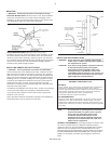
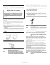
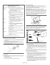
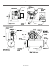
FILTER INSPECTION & CLEANING _____________________
1. Unscrew and remove the wing nut (A) securing the filter housing (B)
to its base (C).
2. Remove the filter housing and withdraw the old filter element (D).
Clean the element with a jet of air or vacuum.
3. Replace the filter element and housing, securing it in place with the
wing nut previously removed.
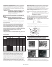
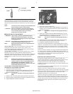
OIL CHANGE ________________________________________
1. Remove the oil drain plug (A) and allow the lubricant to drain into a
suitable container.
2. Replace the oil drain plug.
3. Follow the filling procedures in OPERATION section.
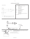
BELT ADJUSTMENT _________________________________
CHECKING BELT TENSION. Check belt tension should be
occasionally, especially if looseness is suspected. New belts must
also be properly tensioned upon installation.
TENSIONING BELTS. Belt tensioning can be achieved by
loosening the motor or engine anchor screws, pushing the motor or
engine away from the pump, and retightening the motor or engine
anchor screws. Some units are equipped with a belt tensioning bolt
that, when turned, pulls the motor or engine away from the pump.
Otherwise, the motor can be easily moved by placing a prying tool
beneath it. A commercially available spreader or other belt
tensioning device can also be helpful.
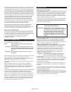
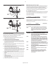
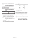
Follow the procedures outlined below to correctly set and measure
belt tension on electric motor and gas engine models including
2340, 2475, and 2545 (with "A" belt type only). Refer to the
following illustration for a visual representation.
1. Lay a straight edge across the top outer surface of the belt drive
from pulley to sheave.
2. At the center of the span, perpendicular to the belt, apply pressure
to the outer surface of the belt with a tension gauge. Force the belt
to the deflection indicated in the BELT TENSION TABLE in the
DIAGRAMS & TABLES section. Compare the reading on the tension
gauge to the table.
Follow the procedures outlined below to correctly set and measure
tension on 7.5 through 30 horsepower models 2545, 7100, 15T and
3000 with "B" and "C" belt types.
1. Measure the span length (t) of the drive.
2. Determine the amount of deflection (in inches) required to measure
deflection force (in pounds) by multiplying the span length (t) by
1/64. For example, a 32” span length multiplied by 1/64 equals 1/2”
of deflection required to measure deflection force.
3. Lay a straight edge across the top outer surface of the belt drive
from pulley to sheave.
4. At the center of the span, perpendicular to the belt, apply pressure
to the outer surface of the belt with a tension gauge. Force the belt
to the predetermined deflection calculated in step 2. Compare the
reading on the tension gauge to the BELT TENSION TABLE in the
DIAGRAMS & TABLES section.
9
http://air.irco.com