


P 7440 Edition 10 3
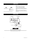
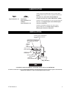
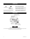
CLUTCH ADJUSTMENT
Disconnect the air supply from the Tool before proceeding.
The Clutch Adjusting Hole Cover has a left-hand thread.
Rotate the Cover clockwise to loosen or remove the Cover.
1. Unscrew the Clutch Adjusting Hole Cover far enough
to expose the clutch adjusting hole in the Clutch
Housing.
2. Insert a 1/4” hex wrench into the Bit Holder and
rotate the clutch mechanism until the area having an
opening between the faces of the Clutch Adjusting
Nut Washer and Clutch Adjusting Nut is visible.
3. Using a screwdriver that has a #1 Phillips tip, insert
the tip of the screwdriver into the opening and rotate
the screwdriver to adjust the Clutch. Rotate the screw-
driver clockwise to decrease Clutch Spring tension
and torque and counterclockwise to increase the ten-
sion and torque.
The most satisfactory adjustment is usually obtained by
using the tool on the actual application and increasing or
decreasing the delivered torque until the desired setting is
reached. In any event, it is recommended that final
adjustment be made by gradual progression.
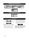
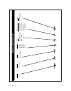
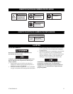
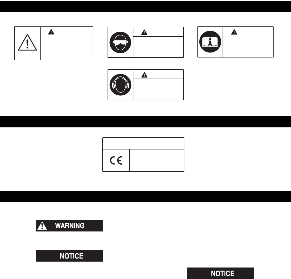
WARNING SYMBOL IDENTIFICATION
WARNING
Always wear eye protection
when operating or performing
maintenance on this tool.
WARNING
Read this manual before
operating tool.
WARNING
Always wear hearing
protection when operating
this tool.
WARNING
This is the safety alert symbol.
It is used to alert you to potential
personal injury hazards. Obey all
safety messages that follow this
symbol to avoid possible injury
or death.
AGENCY SYMBOL IDENTIFICATION
Indicates compliance with
relevant CE directives.
European Community Mark
ADJUSTMENTS