


P 7440 Edition 10 31
DISASSEMBLY
General Instructions
1. Do not disassemble the tool any further than neces-
sary to replace or repair damaged parts.
2. Whenever grasping a tool or part in a vise, always use
leather-covered or copper-covered vice jaws to protect
the surface of the part and help prevent distortion.
This is particularly true of threaded members and
housings.
3. Do not remove any part which is a press fit in or on a
subassembly unless the removal of that part is neces-
sary for repairs or replacement.
4. Do not disassemble the tool unless you have a com-
plete set of gaskets and o-rings for replacement.
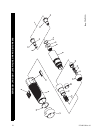
Disassembly of the Tool
Each Series QS Lever Inline Screwdriver is made using
four modules or units which include a motor housing unit,
a motor unit, a clutch with bit holder unit and a combined
gearing with spindle unit. The tool can be disassembled for
repairs to each individual unit without disturbing the other
units. To separate the modules, proceed as follows:
The thread in the following step is a left hand thread.
Rotate the Bit Finder or Housing Cap clockwise to remove
it.
1. For models with Bit Finder Bit Holders, unscrew and
remove the Non-Rotating Bit Finder (92).
For models with Quick Release Bit Holders, unscrew
and remove the Clutch Housing Cap (98). Use a thin
blade screwdriver to spiral the Retaining Ring (91)
out of the groove in the end of the Bit Holder (84).
Being careful not to loose the Bit Retaining Ball (85),
slide the Spring Seat (90), Retaining Sleeve Spring
(89) and the Bit Retaining Sleeve (88) off the Bit
Holder.
The thread in the following step is a left hand thread.
Rotate the Cover clockwise to remove it.
2. Unscrew and remove the Clutch Adjusting Hole Cover
(97). There are two sets of threads with a non-threaded
section between them on the ClutchHousing (82).
3. Using external retaining ring pliers or a thin blade
screwdriver, remove the Grip Retaining Ring (96)
from the groove in the Clutch Housing.
4. Pull the Housing Grip (93) of the front end of the tool.
The thread in the following step is a left hand thread.
Rotate the Clutch Housing clockwise to remove it.
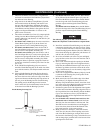
5. Clamp the Inlet Bushing (16) in leather-covered or
copper-covered vise jaws and using a 1-1/16” wrench
on the flats of the Gear Case (43) and the Clutch
Housing Spanner Wrench (Part No. TRH-478) in the
clutch housing slot, unscrew and remove the Clutch
Housing.
6. Push on the output end of the Bit Holder (85) to
remove it from the Clutch Housing (82).
7. For Models with Lever Start, slide the Shutoff Spacer
(87) and Wave Washer (87A) off the Bit Holder.
8. If the Clutch Housing Bearing (83)is worn and must
be replaced, press it from the Clutch Housing.
9. Carefully remove the Clutch Assembly or Clutch Shaft
(81), the Clutch Input Driver (47 or 66), the Clutch
Return Spring (46 or 65), and the Push Rod (67).
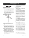
10. Lightly grasp the flats of the Gear Case in leather-cov-
ered or copper-covered vise jaws with the Inlet Bush-
ing upward.
11. Place a 1-3/16” open end wrench on the flats of the
Back Cap (6) to prevent it from rotating, and use a 3/
4” wrench to unscrew and remove the Inlet Bushing.
12. Lift the Exhaust Diffuser (15) off the Back Cap.
13. If the Throttle Valve Spring (14) did not come out of
the tool with the Inlet Bushing, use needle nose pliers
to remove it and the Throttle Valve (13) from the
Motor Housing (1).
14. To remove the Throttle Valve Seat, insert a hooked
tool through the central opening of the Seat and pull it
from the Motor Housing.
15. Using a 1/16” pilot punch, tap the Throttle Lever Pin
(11) out of the Back Cap and remove the Throttle
Lever (10).
16. Pull the Throttle Plunger (5) out of the Motor Hous-
ing and remove the assembly from the vise.
17. Holding the assembly horizontally, remove the Back
Cap, the Memory Chip (9) (if included with the tool),
the Back Cap Gasket (7) and the Shutoff Valve (20) (if
included with the tool).
18. If the Muffler Elements (8) need to be cleaned or
replaced, pull them out of the Back Cap.
19. Grasp the flats at the inlet end of the Motor Housing
in leather-covered or coper-covered vise jaws, and
using a 1-1/16” wrench on the flats of the Motor Hous-
ing, unscrew and separate the Gear Case from the
Motor Housing.
20. Set the assembled Gear Case on the workbench.
21. Remove the Motor Clamp Washer (33) and the Motor
Seal (32) from the assembled motor in the Housing.
22. Tap the Motor Housing on a wood block to remove
the Motor Assembly from the Housing.
Disassembly of the Adjustable Shutoff Clutch
1. Using a thin blade screwdriver, pry the Clutch Adjust-
ing Nut Stop (64) off the end of the Clutch Shaft (52).
MAINTENANCE (Continued)