


36 P7440 Edition 10
3. Lubricate the Motor Seal (32) with o-ring lubricant
and install it around the Front End Plate (29) and into
the undercut in the Housing.
4. Align the tab of the Motor Clamp Washer (33) with
the internal notch in the Housing and install it over
the rotor hub and End Plate Alignment Pin against
the Motor Seal. Make certain the Pin enters the hole
in the Washer and the Washer is flat against the Seal.
5. Apply some Ingersoll-Rand No. 67 Grease to the
spline on the rotor shaft.
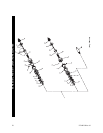
6. Thread the assembled Gear Case (43), output spindle
trailing, into the Motor Housing and using a 1-1/16”
wrench, tighten the joint between 15 and 20 ft-lbs. (20
and 27 Nm) torque.
7. For Models with a Clutch, place the narrow end of the
Clutch Return Spring (46 or 65) in the Gear Case
against the inner race of the Spindle Bearing (44).
8. For Models with Direct Drive, insert the hex end of
the Clutch Shaft (81) that does not have the step, into
the hex recess of the Spindle Assembly (42).
For Models with a Clutch, place the hex drive end of
the Clutch Input Driver (47 or 66) on the Spring and
compress the Spring until the hex on the Driver enters
the hex recess in the Spindle Assembly (42). While
holding the Driver in position, engage the raised bar
on the face of the Driver with the jaw of the Cam Jaw
(54 or 70).
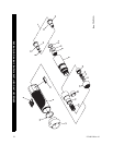
9. If the Clutch Housing Bearing (83) was removed,
stand the Clutch Housing (82) on the table of an arbor
press with the smaller, externally threaded end down-
ward.
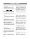
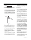
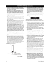
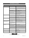
10. Using a Needle Bearing Inserting Tool as shown in
Dwg. TPD786 with a 0.030” (0.76 mm) thick washer
that clears the inner bore and outer edge of the Bear-
ing inserted between the Bearing and stop surface on
the tool, press the Bearing into the Clutch Housing.
The trailing end of the Bearing must be between
0.025” and 0.035” (0.63 and 0.89 mm) below the face
of the bore into which the Bearing is pressed.
Needle Bearing Inserting Tool
11. For Models with Lever Start, slide the Wave Washer
(87A) followed by the Shutoff Spacer (87) onto the
hub of the Bit Holder (84) and insert the Bit Holder
into the large end of the Clutch Housing (82) and
push the output end through the Clutch Housing
Bearing.
For Models with Lever Permit, insert the Bit Holder
(84) into the large end of the Clutch Housing (82) and
push the output end through the Clutch Housing
Bearing
The following step has parts with a left-hand thread.
Rotate the components counterclockwise to tighten them.
12. Install the assembled Clutch Housing over the clutch
components and thread it onto the Gear Case. Using
a 1-1/16” wrench on the flats of the Gear Case and the
Clutch Housing Spanner Washer (Part No. TRH-478)
in the clutch housing slot, tighten the joint between 15
and 20 ft-lbs. (20 and 27 Nm) torque.
13. Invert the assembled tool in the vise jaws and lightly
grasp the flats on the Gear Case with the inlet end of
the tool upward.
14. Insert a 5/8” dowel through the opening in the Back
Cap (6), and using the dowel as an alignment device,
install the three Muffler Elements (8) in the cavity of
the Back Cap. Make certain the notches in the outer-
edge of the Elements fit over the memory chip pocket
in the bottom of the Cap.
15. If the tool is equipped with a Memory Chip (9), install
it (with the leads entering first) in the pocket at the
bottom of the Back Cap.
16. Make certain the tab on the inside edge of the Back
Cap Gasket (7) is aligned with the pocket for the
Memory Chip and install the Gasket, metal face lead-
ing, in the recess of the Back Cap against the face with
the cavity containing the Muffler Elements.
17. Position the gasket end of the alignment dowel against
the inlet hub on the Motor Housing. Align the flats on
the Cap with the flats on the Housing. Orient the Back
Cap to clear the Reverse Lever (19) and slide the
Back Cap Assembly off the alignment dowel and onto
the Motor Housing.
18. For all Models with a Shutoff Clutch and Lever Per-
mit Models with a Cushion Clutch, install the Push
Rod (34) into the central hole in the inlet hub. The
Rod will enter the assembled motor and disappear
from view when released. Install the Shutoff Valve
(20), small end first, in the same opening.
19. Being careful not to damage it, insert the Throttle
Valve Seat (12) into the central opening at the inlet
end of the Motor Housing at an angle until it clears
the threads in the Housing. Using a rod with a flat end
and no sharp edges, push the Seat to the bottom of the
opening until it seats flush.
(Dwg. TPD786)
SHOULDER TO
REGULATE DEPTH
PILOT TO FIT I.D. OF BEARING.
LENGTH OFPILOT TO BE
APPROXIMATELY 1/8” LESS THAN
LENGTH OF BEARING
MAINTENANCE (Continued)