


P 7440 Edition 10 35
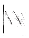
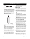
2. Drop the twelve Clutch Balls (69) into the Cam Jaw
forming a ring around the Clutch Shaft.
3. Lay a bead of Ingersoll-Rand No. 28 Grease, approxi-
mately 2 to 3 cc, on top of the Clutch Balls and then
bring the Clutch Shaft and Cam Jaw together captur-
ing the Balls between them.
4. While holding the Shaft and Jaw together, slide the
Clutch Cam Ball Driver (71), large end leading, onto
the Clutch Shaft until it is against the Cam Jaw.
5. Rotate the Driver to align the large hole through one
wall of the Driver with the comparable size opening of
the cross hole through the Clutch Shaft. Push the
Clutch Cam Ball Driver Retaining Pin (73) into the
hole to lock the Driver in position on the Clutch Shaft.
6. Apply a coating of Ingersoll-Rand No. 28 Grease to
each of the eleven Clutch Cam Balls (72).
7. Holding the assembled Clutch Shaft with the Clutch
Cam Ball Driver upward, insert a lubricated Ball into
each of the eleven ball pockets in the Driver.
8. Slide the Cam Ball Seat (74), large end leading, onto
the Shaft against the Balls. Follow with the Clutch
Spring (75), Spring Seat (76), Thrust Bearing (77) and
the Clutch Adjusting Nut Washer (78) with the
smooth face leading.
9. Thread the Clutch Adjusting Nut (79), smooth face
trailing, onto the Clutch Shaft.
10. Insert the tip of a #1 Phillips Head Screwdriver into
the adjustment opening between the Clutch Adjusting
Nut and the Clutch Adjusting Nut Washer. Rotate the
screwdriver counterclockwise and thread the Adjust-
ment Nut onto the Clutch Shaft until the external
groove for the Clutch Adjusting Nut Stop (80) is visi-
ble.
11. Install the Nut Stop in the groove.
Assembly of the Adjustable Shutoff Clutch
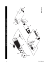
1. Hold the Clutch Shaft (52) in your hand with the large
end upward.
2. Insert the Automatic Shutoff Plunger Return Spring
(49) into the central opening in the large end of the
Clutch Shaft. Use a 1/8” dowel to push the Spring
below the cross hole for the Automatic Shutoff Pin
(50).
3. Insert the Automatic Shutoff Pin Spring (51) in the
end hole of the Automatic Shutoff Pin opposite the
pointed end. Rotate the Spring a little to keep it in the
hole.
4. Drip one or two drops of Ingersoll-Rand No. 10 Oil
into the central hole with the Plunger Return Spring.
5. Position the Shutoff Pin, Spring leading, in the cross
hole on the large end of the Clutch Shaft with the hole
in the Shutoff Pin aligned with the central hole con-
taining the Return Spring.
6. Push on the pointed end of the Shutoff Pin to depress
the Spring while inserting the Automatic Shutoff
Plunger (48) into the central opening with the Return
Spring. The smaller center portion of the Shutoff
Plunger will allow the Shutoff Pin to spring outward
and capture the components within the Clutch Shaft
when properly positioned.
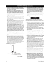
7. Insert the small end of the Clutch Shaft into the end
of the Cam Jaw (54) having the large opening and
slide the Shaft about half way into the Jaw.
8. Drop the twelve Clutch Balls (53) into the Cam Jaw
forming a ring around the Clutch Shaft.
9. Lay a bead of Ingersoll-Rand No. 28 Grease, approxi-
mately 2 to 3 cc, on top of the Clutch Balls and then
bring the Clutch Shaft and Cam Jaw together captur-
ing the Balls between them.
10. While holding the Shaft and Jaw together, slide the
Clutch Cam Ball Driver (55), large end leading, onto
the Clutch Shaft until it is against the Cam Jaw.
11. Rotate the Driver to align the large hole through one
wall of the Driver with the comparable size opening of
the cross hole through the Clutch Shaft. Push the
Clutch Cam Ball Driver Retaining Pin (57) into the
hole to lock the Driver in position on the Clutch Shaft.
12. Apply a coating of Ingersoll-Rand No. 28 Grease to
each of the three Clutch Cam Balls (56).
13. Holding the assembled Clutch Shaft with the Clutch
Cam Ball Driver upward, insert a lubricated Ball into
each of the three ball slots in the Driver.
14. Slide the Cam Ball Seat (58), large end leading, onto
the Shaft against the Balls. Follow with the Clutch
Spring (59), Spring Seat (60), Thrust Bearing (61) and
the Clutch Adjusting Nut Washer (62) with the
smooth face leading.
15. Thread the Clutch Adjusting Nut (63), smooth face
trailing, onto the Clutch Shaft.
16. Insert the tip of a #1 Phillips Head Screwdriver into
the adjustment opening between the Clutch Adjusting
Nut and the Clutch Adjusting Nut Washer. Rotate the
screwdriver counterclockwise and thread the Adjust-
ment Nut onto the Clutch Shaft until the external
groove for the Clutch Adjusting Nut Stop (64) is visi-
ble.
17. Install the Nut Stop in the groove.
Assembly of the Tool
1. Lightly grasp the flats at the inlet end of the Motor
Housing (1) in leather-covered or copper-covered vise
jaws with the motor bore upward.
2. Grasp the spline of the Rotor (27) in the assembled
motor and after aligning the End Plate Alignment Pin
(30) with the internal notch in the motor end of the
housing bore, insert the assembled motor into the
Motor Housing. Make certain the motor is far enough
into the Housing to have the undercut below the inter-
nal housing thread visible.
MAINTENANCE (Continued)