


P 7440 Edition 10 33
Planet Gear Head Assembly (38) and the Planet Gear
Head Spacer (41).
3. Using snap ring pliers, remove the Spindle Bearing
Retaining Ring (45).
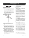
4. Stand the Gear Case on the table of an arbor press
with the output spindle upward. Using a rod that
neatly fits inside the internal hex of the Spindle (42),
press the Spindle Assembly out of the Spindle Bearing
(44).
Do not remove the Bearing in the following step unless you
have a new replacement available for installation. The
Bearing will be damaged by the removal process.
5. Invert the Gear Case on the table of an arbor press so
that the end face having four notches makes contact
with the table. Using a rod against the inner race of
the Spindle Bearing, press the Bearing from the Gear
Case.
6. If the Spindle Bearing Seat (46) must be replaced, use
a small, thin blade screwdriver to spiral it out of the
groove in the Gear Case.
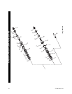
Disassembly of the Motor
1. Using snap ring pliers, remove the Rear End Plate
Assembly Retainer (23) from the shaft of the Rotor
(27).
2. Pull the Rear End Plate Face Plate (22) and Rear End
Plate Assembly (21) off the hub of the Rotor.
3. Lift the Cylinder (24) from the Rotor.
4. Remove the Vanes (28) from the Rotor.
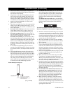
5. Support the Front End Plate Assembly (29), as near
the rotor body as possible, on the table of an arbor
press and press the Rotor from the Front Rotor Bear-
ing (31). Remove the Bearing from the Front End
Plate.
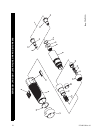
Disassembly of the Housing
1. Pull the Reverse Lever (19) off the inlet end of the
Motor Housing (1).
2. Using a #2 Phillips Head Screwdriver, unscrew and
remove the Housing Screw (3).
3. Insert a 5/16” wooden dowel between 6 and 8 inches
long, into the inlet end of the Motor Housing and
push the Reverse Valve Assembly (4) out the motor
end of the Housing.
4. Use a hooked tool to pull the Housing O-ring (2) out
of the Motor Housing.
ASSEMBLY
General Instructions
1. Always press on the inner ring of a ball-type bearing
when installing the bearing on a shaft.
2. Always press on the outer ring of a ball-type bearing
when pressing the bearing into a bearing recess.
3. Whenever grasping a tool or part in a vise, always use
leather-covered or copper-covered vise jaws to protect
the surface of the part and help prevent distortion.
This is particularly true of threaded members and
housings.
4. Except for bearings, always clean every part and wipe
every part with a thin film of oil before installation.
5. Apply o-ring lubricant to all o-rings before final
assembly.
6. Check every bearing for roughness. If an open bearing
must be cleaned, wash it thoroughly in a clean, suitable
cleaning solution and dry with a clean cloth.
Sealed or
shielded bearings should never be cleaned.
Work
grease into every open bearing before installation.
Assembly of the Housing
1. Lubricate the Housing O-ring (2) with o-ring lubricant
and install it at the bottom of the cylinder bore in the
Motor Housing (1).
2. Inspect the face and o-ring on the hub of the Reverse
Valve Assembly (4) for nicks or damage. Replace the
Reverse Valve Assembly if any damage is evident.
3. Lubricate the o-ring on the hub of the Reverse Valve
Assembly with o-ring lubricant and insert the Assem-
bly, o-ring end leading, into the cylinder bore of the
Motor Housing. Push the Assembly toward the bot-
tom of the cylinder bore until it “snaps” into its proper
location.
4. Rotate the Valve inside the Housing until the
threaded hole into the side of the Valve for the Motor
Housing Screw (3) aligns with the hole in the Motor
Housing.
5. Using a #2 Phillips Head Screwdriver, thread the
Motor Housing Screw into the Reverse Valve Assem-
bly through the Housing until the underside of the
screw head stops against the Housing. Back the Screw
out of the Valve between 1/4 and 1/2 turn.
6. Align the open end of the slot inside the Reverse
Lever (19) with the head of the Housing Screw. From
the inlet end of the Housing, slide the Lever onto the
Housing, making certain the screw head enters the
slot, and move it along the Housing until it stops
against the housing shoulder.
7. Rotate the Lever to make certain the Valve only has
slight resistance.
Assembly of the Motor
1. Place the Front End Plate (29) on the splined shaft of
the Rotor (27) with the bearing recess away from the
rotor body.
2. Place the Front Rotor Bearing (31) onto the shaft and
using a sleeve or piece of tubing that contacts the
inner race of the Bearing, press the Bearing onto the
MAINTENANCE (Continued)