


32 P7440 Edition 10
2. Insert the tip of a #1 Phillips Head Screwdriver into
the adjustment opening between the Clutch Adjusting
Nut (63) and the Clutch Adjusting Nut Washer (62).
Rotate the screwdriver clockwise to thread the Adjust-
ment Nut off the Clutch Shaft.
In the following step, the Clutch Cam Balls will be free to
fall from the assembly when the Cam Ball Seat is moved.
Make certain the Balls fall into a non-damaging container.
3. Holding the assembly over a small pasteboard box,
slide the Adjusting Nut Washer, the Thrust Bearing
(61), the Spring Seat (60), the Clutch Spring (59) and
the Cam Ball Seat (58) off the Clutch Shaft. Allow the
three Clutch Cam Balls (56) to fall into the paste-
board box.
4. The Clutch Cam Ball Driver (55) has a cross hole that
is larger on one side than the other. Insert a 1/16” drill
shank or piece of wire into the smaller hole and gently
push the Clutch Driver Retaining Pin (57) out of the
larger hole and out of the Driver and the Clutch Shaft.
In the following step, the Clutch Balls will be free to fall
from the assembly when the Cam Jaw is moved along the
Clutch Shaft. Make certain the Balls fall into a non-
damaging container.
5. Holding the assembly over a small pasteboard box,
and using care to drop the twelve Clutch Balls (53)
into the box, slide the Clutch Cam Ball Driver and
Cam Jaw (54) off the Clutch Shaft. If grease held
some of the Balls inside the jaw cavity, remove them.
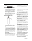
6. With the large end of the Clutch Shaft downward,
depress the Automatic Shutoff Pin (50) with varying
amounts of finger pressure while tapping the large
end edge of the Clutch Shaft on a piece of wood until
the Automatic Shutoff Plunger (48) protrudes slightly
from the end of the Shaft. Grasp the Plunger and
carefully pull it out of the Clutch Shaft.
7. Remove the Automatic Shutoff Pin and Automatic
Shutoff Pin Spring (51) from the Clutch Shaft. The
Pin Spring should remain in the pin recess when the
Pin is removed. To separate the Spring from the Pin,
gently rotate the Spring while pulling it from the
recess to avoid elongating the Spring.
8. Using a hooked tool, reach into the opening in the
end of the Clutch Shaft and carefully pull the Auto-
matic Shutoff Plunger Return Spring (49) out of the
Shaft without elongating the Spring.
Disassembly of the Adjustable Cushion Clutch
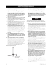
1. Using a thin blade screwdriver, pry the Clutch Adjust-
ing Nut Stop (80) off the end of the Clutch Shaft (68).
2. Insert the tip of a #1 Phillips Head Screwdriver into
the adjustment opening between the Clutch Adjusting
Nut (79) and the Clutch Adjusting Nut Washer (78).
Rotate the screwdriver clockwise to thread the Adjust-
ment Nut off the Clutch Shaft.
In the following step, the Clutch Cam Balls will be free to
fall from the assembly when the Cam Ball Seat is moved.
Make certain the Balls fall into a non-damaging container.
3. Holding the assembly over a small pasteboard box,
slide the Adjusting Nut Washer, the Thrust Bearing
(77), the Spring Seat (76), the Clutch Spring (75) and
the Cam Ball Seat (74) off the Clutch Shaft. Allow the
eleven Clutch Cam Balls (72) to fall into the paste-
board box.
4. The Clutch Cam Ball Driver (71) has a cross hole that
is larger on one side than the other. Insert a 1/16” drill
shank or piece of wire into the smaller hole and gently
push the Clutch Driver Retaining Pin (73) out of the
larger hole and out of the Driver and the Clutch Shaft.
In the following step, the Clutch Balls will be free to fall
from the assembly when the Cam Jaw is moved along the
Clutch Shaft. Make certain the Balls fall into a non-
damaging container.
5. Holding the assembly over a small pasteboard box,
and using care to drop the twelve Clutch Balls (69)
into the box, slide the Clutch Cam Ball Driver and
Cam Jaw (70) off the Clutch Shaft. If grease held
some of the Balls inside the jaw cavity, remove them.
Disassembly of the Gearing
1. Using snap ring pliers, remove the Gear Retainer (35)
from the motor end of the Gear Case (43) and remove
the Gear Head Spacer (36) as well.
2. For Series QS1L02, QS1T02, QS1L05, QS1T05,
QS1L10 and QS1T10, lightly rap the motor end of the
Gear Case on a wooden work bench top to remove the
three Planet Gears (39), the Planet Gear Head
Assembly (38) and the Planet Gear Head Spacer (41).
For Series QS1L17, QS1T17, QS1L20 and QS1T20,
lightly rap the motor end of the Gear Case on a
wooden work bench top to remove the three Planet
Gears (39), The Gear Head Pinion (40), the Planet
Gear Head Assembly (38) and the Planet Gear Head
Spacer (41).
For Series QS1L28 and QS1T28, lightly rap the motor
end of the Gear Case on a wooden work bench top to
remove the Planet Gear Head Drive Plate (37), the
MAINTENANCE (Continued)