


34 P7440 Edition 10
shaft until the Front End Plate nearly contacts the
rotor body.
In the following step, the measurement must be made at
the end corner of the large rotor body.
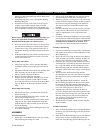
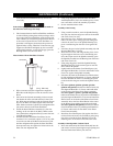
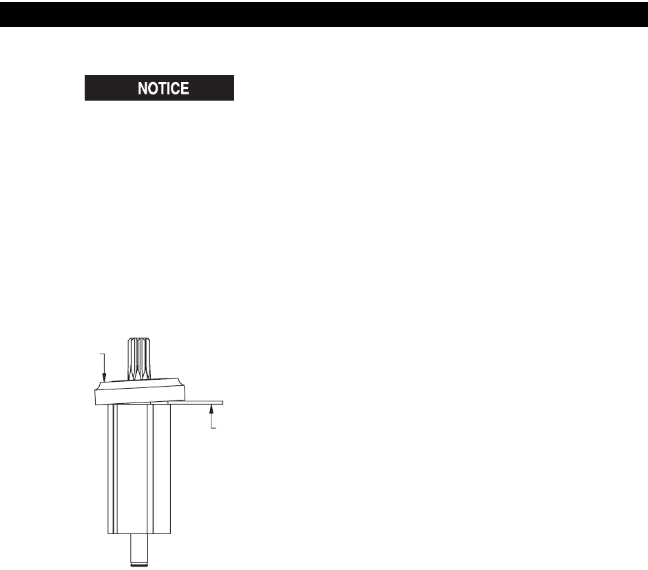
3. The clearance between the Front End Plate and Rotor
is critical. While pressing down with your finger on the
outer edge of the Front End Plate on the bearing side,
insert a 0.004” (0.1 mm) feeler gauge between the face
of the rotor body and the face of the End Plate at a
point that is 180 degrees from where the pressure is
applied. Refer to Dwg. TPA1740. To increase the gap,
support the End Plate and lightly tap the rotor shaft
with a plastic hammer; to decrease the gap, press the
Bearing farther onto the rotor shaft.
Measurement of Front End Plate Clearance
4. Wipe each Vane (28) with a light film of Ingersoll-
Rand No.10 Oil and place a Vane in each slot in the
Rotor.
5. One end of the Cylinder Assembly (24) has a notch
that breaks the outer wall and end face of the Cylin-
der. With that end trailing, install the Cylinder Assem-
bly over the Rotor and Vanes against the Front End
Plate. Make certain the Cylinder Front Alignment Pin
(26) enters the hole in the Front End Plate.
6. Install the Rear End Plate Assembly (21), flat face
leading, on the rear hub of the Rotor. Make certain
the Cylinder Rear Alignment Pin (25) enters the hole
in the Rear End Plate.
7. Examine the Rear End Plate Face Plate (22) for
scratches. If it is scratched, replace it. If it is not, slide
it onto the rear hub of the Rotor and onto the Cylin-
der Rear Alignment Pin against the Rear End Plate.
Some pressure may be required to fit the hole in the
Plate onto the Alignment Pin.
8. Using snap ring pliers, install the Rear End Plate
Assembly Retainer (23) in the annular groove on the
rear rotor hub to secure the assembly in position.
9. Set the assembled motor aside.
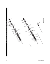
Assembly of the Gearing
1. Using a small screwdriver, work the Spindle Bearing
Seat (46) into the internal groove nearest the notched
end of the Gear Case (43).
2. Stand the Gear Case, notched end upward, on the
table of an arbor press. Using a piece of tubing that
contacts the outer race of the Spindle Bearing (44),
press a new Bearing into the Gear Case against the
Seat.
3. Lubricate the gears in the Spindle Assembly (42) with
Ingersoll-Rand No. 67 Grease.
4. Invert the Gear Case and using another piece of tub-
ing that supports the inner race of the Bearing and
clears the output end of the Spindle Assembly, press
the Spindle Assembly into the Bearing from the motor
end of the Gear Case.
5. Using snap ring pliers, install the Spindle Bearing
Retaining Ring (45) in the external groove near the
driver end of the spindle.
6. Lightly lubricate the Planet Gear Head Spacer (41)
with Ingersoll-Rand No. 67 Grease and install it in the
Gear Case against the Spindle Assembly.
7. Lubricate the shafts of the Planet Gear Head Assem-
bly (38) with Ingersoll-Rand No. 67 Grease and install
the Gear Head in the Gear Case meshing the spline
on the shaft with the gear teeth in the Spindle Assem-
bly.
8. For Series QS1L02, QS1T02, QS1L05, QS1T05,
QS1L10 and QS1T10, lubricate the Planet Gears (39)
with Ingersoll-Rand No. 67 Grease and install them
on the shafts of the Planet Gear Frame Assembly.
For Series QS1L17, QS1T17, QS1L20 and QS1T20,
lubricate the Planet Gears (39) and Gear Head Pinion
(40) with Ingersoll-Rand No. 67 Grease and install the
Planet Gears on the shafts of the Planet Gear Frame
Assembly. Insert the Gear Head Pinion in the center
of the Planet Gears making certain the teeth mesh.
For Series QS1L28 and QS1T28, lubricate the Planet
Gear Head Drive Plate (37) with Ingersoll-Rand No.
67 Grease and install it on the shafts of the Planet
Gear Frame Assembly.
9. Install the Gear Head Spacer (36) against the Gears
or Drive Plate and secure the assembly by using snap
ring pliers to install the Gear Retainer (35) in the
internal groove at the motor end of the Gear Case.
Assembly of the Adjustable Cushion Clutch
1. Insert the small end of the Clutch Shaft (68) into the
end of the Cam Jaw (70) having the large opening and
slide the Shaft about half way into the Jaw.
(Dwg. TPA1740)
PRESSURE
FEELER
GAUGE
MAINTENANCE (Continued)