


30 P7440 Edition 10
Always wear eye protection when operating or performing
maintenance on this tool.
Always turn off the air supply and disconnect the air
supply hose before installing, removing or adjusting any
accessory on this tool, or before performing any
maintenance on this tool.
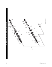
LUBRICATION
Each time a Series QS Screwdriver is disassembled for
maintenance and repair or replacement of parts, lubricate
the tool as follows:
1. Coat all exposed gears with Ingersoll-Rand No. 67
Grease and work some of the Grease into the gearing
of the Spindle Assembly (42).
2. Work approximately 6 to 8 cc of Ingersoll-Rand No.
28 Grease into the ball pockets, jaws, adjusting nut
lock and shaft threads of the clutch mechanism.
3. Use Ingersoll-Rand No. 10 Oil to lubricate the motor.
Inject approximately 1 to 2 cc of oil into the air inlet
before attaching the air hose to the tool.
SPEED ADJUSTMENT
In addition to adjustable clutches for controlling torque,
Series QS Lever Inline Screwdrivers are furnished with the
ability to precisely control speed, within certain ranges.
Setting the speed requires a tachometer.
Therefore, the adjustment, although simple, should only be
attempted by a competent technician using the proper
equipment.
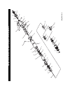
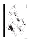
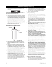
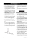
The Back Cap (6) has a small, molded stud on the end face
of the Cap nearest the Exhaust Diffuser (15). That stud
controls the radial location of the Diffuser which controls
the opening size of the exhaust ports. Take an initial
reading of the tool speed by applying a tachometer with a
convex tip to the inside of the Bit Holder (84). Using the
procedure required to activate the motor of your particular
model tool, bring the motor to maximum free speed.
After determining the actual velocity, shut off the air
supply and disconnect the air line. Use a 3/4” wrench to
loosen the Inlet Bushing. The longest slot in the Exhaust
Diffuser will contain the molded stud on the Back Cap.
Rotate the Diffuser to open the exhaust ports to increase
speed or rotate it to restrict the exhaust to reduce speed.
Being careful not to allow the Diffuser to damage the
molded stud, tighten the Inlet Bushing to 15 ft-lbs. (20
Nm) torque. Connect the air line and restore the air supply
and check the velocity again. Determine which direction
you need to rotate the Diffuser to obtain the desired speed
and then rotate it accordingly. Best results are achieved by
using gradual increments and frequent tachometer
readings. Be sure to turn off the air supply and disconnect
the line when making adjustments.
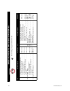
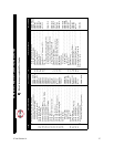
CLUTCH SPRING SELECTION CHART
Tool
Free
Speed
(rpm)
TORQUE RANGE (Soft Draw)
Light Clutch
Spring (Orange)
Medium Clutch
Spring (Red)
Heavy Clutch
Spring (Green)
All Series QS
Inline
Screwdrivers
2800
1.7 to 9.7 in-lbs.
(0.19 to 1.1 Nm)
--------------------
--------------------
--------------------
--------------------
2000
1.7 to 9.7 in-lbs.
(0.19 to 1.1 Nm)
7.9 to 22.1 in-lbs.
(0.89 to 2.50 Nm)
--------------------
--------------------
1710
1.7 to 9.7 in-lbs.
(0.19 to 1.1 Nm)
7.9 to 27.3 in-lbs.
(0.89 to 3.08 Nm)
--------------------
--------------------
1000
1.7 to 9.7 in-lbs.
(0.19 to 1.1 Nm)
7.9 to 27.3 in-lbs.
(0.89 to 3.08 Nm)
13.3 to 40.0 in-lbs.
(1.50 to 4.52 Nm)
500
1.7 to 9.7 in-lbs.
(0.19 to 1.1 Nm)
7.9 to 28.3 in-lbs.
(0.89 to 3.20 Nm)
13.3 to 47.8 in-lbs.
(1.50 to 5.40 Nm)
250
1.7 to 9.7 in-lbs.
(0.19 to 1.1 Nm)
7.9 to 28.3 in-lbs.
(0.89 to 3.20 Nm)
13.3 to 47.8 in-lbs.
(1.50 to 5.40 Nm)
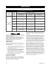
MAINTENANCE