15
Installing/Changing Blades
Disconnect machine from
power source. Blade teeth are sharp, use care
when handling the blade. Failure to comply may
cause serious injury.
1. Disconnect machine from power source.
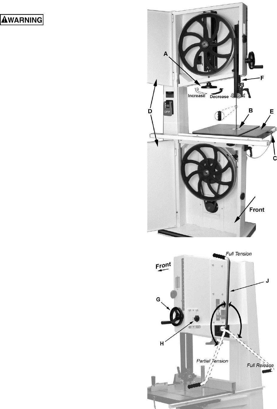
2. Place the mode selection lever (J, Fig. 18) in
the Full Release (Blade Change) position.
Note 1: When changing the position of the
mode selection lever, the machine must be
turned off.
Note 2: The blade tension handwheel
(A, Fig. 17) is primarily used for initial blade
tension adjustments (described on following
page).
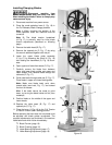
3. Remove the table insert (B, Fig. 17).
4. Remove the tapered pin (C, Fig. 17) by using
the wrench attached together with the pin.
5. Lower the upper blade guide assembly
(F, fig. 17) by loosening the knob (H, Fig. 18)
and rotating the handwheel (G, Fig. 18) clock-
wise.
6. Open upper and lower front doors (D, Fig. 17).
7. Carefully remove the blade from between
upper and lower blade guides and upper and
lower wheels; then remove blade through the
table slot (E, Fig. 17).
8. Guide new blade through table slot (E, Fig. 17).
Place blade in upper and lower blade guides.
Note: Make sure blade teeth point down
toward table (see inset, Fig. 17), and toward
the front of the saw.
Hint: If the teeth cannot be made to point
down, try turning the blade inside out first, then
reattempt.
9. Position blade on the middle of the upper and
lower wheels.
10. Replace the table insert (B, Fig. 17) and
tapered pin (C, Fig. 17).
11. Place the lever (J, Fig. 18) to the Full Tension
or Partial Tension (Idle/Tracking) position.
Before operating the band saw, the new blade must
be adjusted and blade guides re-adjusted. The
required adjustments are contained in the sections
listed below and which follow immediately:
Blade Tension (page 16)
Blade Tracking (page 16)
Upper Bearing Adjustment (page 17)
Lower Bearing Adjustment (page 18)
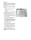
Figure 17
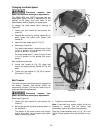
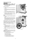
Figure 18


