18
Lower Bearing Adjustments
Unplug the machine from power
source before making any adjustments! Blade
teeth are sharp - use care when working near
the saw blade. Failure to comply may cause
serious injury.
Note: Blade tension and tracking must be properly
adjusted prior to bearing guide setup. Refer to the
Blade Tension section (page 16).
1. Place the mode selection lever (J, Fig. 18) in
the Full Tension position.
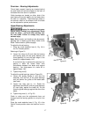
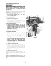
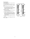
Referring to Figure 23:
2. Loosen the thumb screw (B).
This will allow the thrust bearing (A) to move
freely and prevent interference with the saw
blade (C) during the following steps.
Guide Gearings Adjustment
3. Loosen the locking handle (D) then turn the
adjustment screw (E) to adjust the assembly
forward or backward until the front of the guide
bearings (F) rest just behind the gullet of the
blade teeth (C and inset).
4. Tighten the locking handle (D).
Thrust Bearing Adjustment
5. With the thumb screw still loose (from Step 1),
slide the thrust bearing and bearing post until
the space between the bearing (A) and the
back edge of the blade (C) is approximately
1/64”.
A convenient way to achieve this spacing is by
placing a dollar bill folded twice (four
thicknesses) between the blade and support
bearing – four thicknesses of a dollar bill is
approximately 1/64”.
6. Tighten the thumb screw (B).
7. Loosen the lock knob (G). Rotate the
adjustment handles (H) until the guide bearings
(F) rest lightly against the blade (C). Do not
force the guide bearings against the side of the
blade.
8. Tighten the lock knob (G).
Check to make sure the adjustments have not
changed and the bearing guides do not pinch the
blade.
Place the mode selection lever (J, Fig. 18) in the
Partial Tension position when the machine is not in
use.
Figure 23


