


A-5
INSTALLATION
RANGER 300 D AND 300 DLX
A-5
ELECTRICAL CONNECTIONS
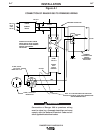
See Figure B.1 in the OPERATION section of this
manual for location of the 115 and 230 volt recepta-
cles, weld output terminals, circuit breakers and
ground stud.
MACHINE GROUNDING
Because the RANGER 300 creates its own power
from its diesel-engine driven generator, and if the
machine is not connected to premises wiring (home,
shop, etc.), you do not need to connect the machine
frame to an earth ground. However, for best protec-
tion against electrical shock, connect a heavy gauge
wire (#8 AWG or larger) from the ground stud located
on the bottom of the output panel (See Figure B.1) to
a suitable earth ground such as a metal pipe driven
into the ground.
Do not ground the machine to a pipe that carries
explosive or combustible material.
------------------------------------------------------------------------
When the Ranger 300 is mounted on a truck or a trail-
er, the machine generator ground stud MUST be
securely connected to the metal frame of the vehicle.
See Figure B.1. The ground stud is marked with the
ground symbol.
If the RANGER 300 is connected to premises wiring
such as a home or shop, it must be properly connect-
ed to the system earth ground.
WELDING CABLE CONNECTIONS
CABLE SIZE AND LENGTH
Be sure to use welding cables that are large enough.
The correct size and length becomes especially
important when you are welding at a distance from the
welder.
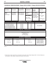
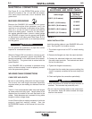
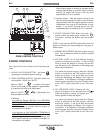
Table A.1 lists recommended cable sizes and lengths
for rated current and duty cycle. Length refers to the
distance from the welder to the work and back to the
welder. Cable diameters are increased for long cable
lengths to reduce voltage drops.
Lincoln Electric offers a welding accessory kit with the
properly specified welding cables. See the
ACCESSORIES section of this manual for more infor-
mation.
WARNING
Table A.1
CABLE INSTALLATION
Install the welding cables to your RANGER 300 as fol-
lows. See Figure B.1 for location of parts.
1. The diesel engine must be OFF to install welding
cables.
2. Remove the flanged nuts from the output terminals.
3. Connect the electrode holder and work cables to
the weld output terminals. The terminals are identi-
fied on the case front.
4. Tighten the flanged nuts securely.
5. Be certain that the metal piece you are welding (the
“work”) is properly connected to the work clamp and
cable.
6. Check and tighten the connections periodically.
• Loose connections will cause the output terminals to
overheat. The terminals may eventually melt.
• Do not cross the welding cables at the output termi-
nal connection. Keep the cables isolated and sepa-
rate from one another.
------------------------------------------------------------------------
TOTAL COMBINED LENGTH OF
ELECTRODE AND WORK CABLES
Cable Length
0-50 Ft. (0-15 meters)
50-100 Ft. (15-39 meters)
100-150 Ft. (30-46 meters)
150-200 Ft. (46-61 meters)
200-250 Ft. (61-76 meters)
Cable Size for
300 Amps
100% Duty Cycle
1/0 AWG
1/0 AWG
2/0 AWG
2/0 AWG
3/0 AWG
CAUTION