GX 271 Chopper
B-3
OPERATION
B-3
CONTROLS AND SETTINGS
All generator/welder controls are located on the
Output Control Panel of the machine case front. Idler
control, and start/stop controls are also on the case
front. See Figure B.1 and the explanations that follow.
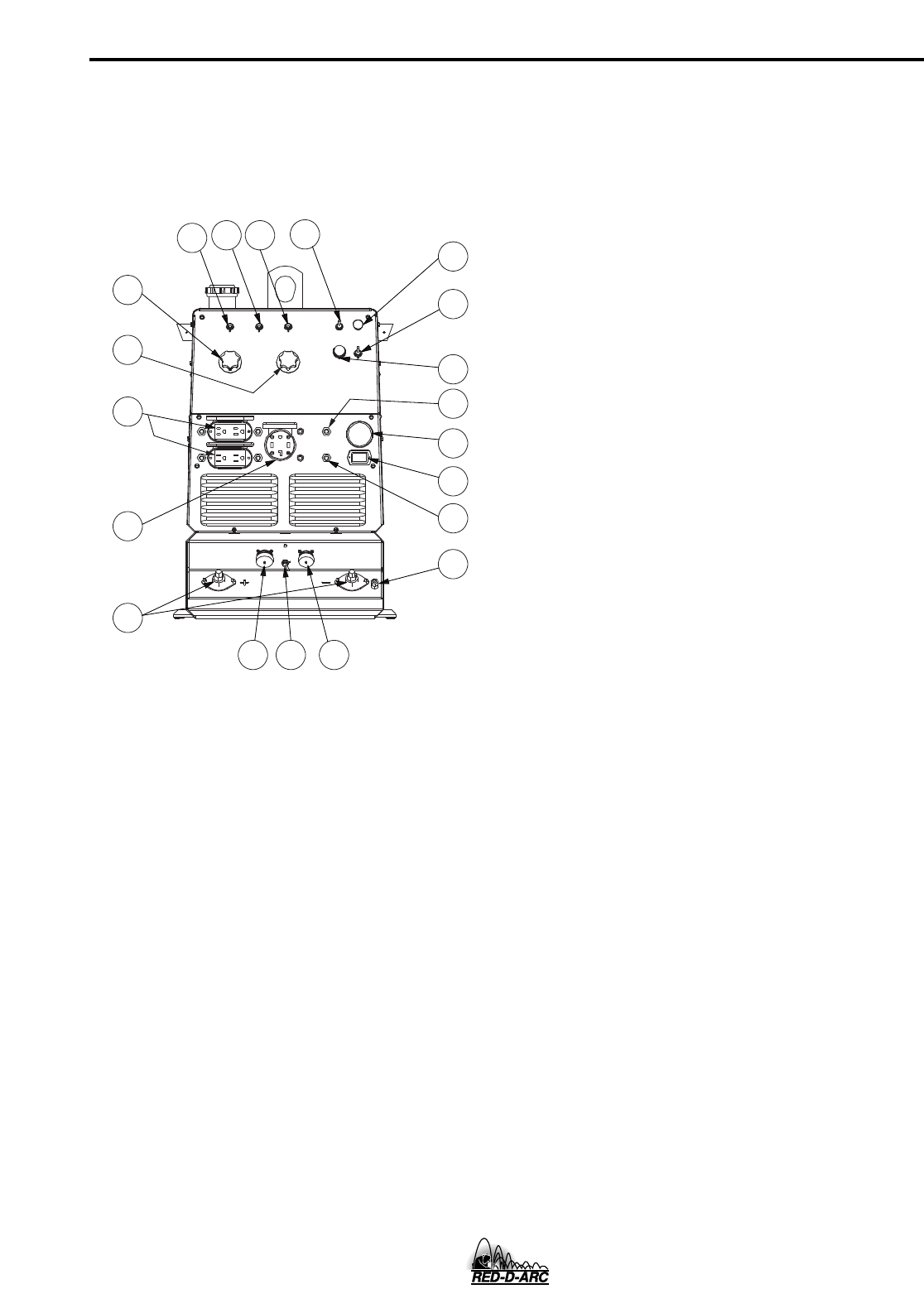
FIGURE B.1
OUTPUT PANEL CONTROLS
WELDER/GENERATOR CONTROLS
See Figure B.1 for the location of the following features:
1. OUTPUT CONTROL: Allows full range adjustment of
welding current or voltage.
2. ARC CONTROL: The “ARC CONTROL” potentiome-
ter is active in two modes: “STICK/TIG” and “WIRE
WELDING” with different purposes in each mode.
3. MODE SWITCH: Selects three possible modes of
welding operation, 1.) CC Stick/Tig welding, 2.) Pipe
welding, and 3.) CV Wire Welding.
4. LOCAL/REMOTE CONTROL SWITCH: Allows the
operator to control welding output at the welding con-
trol panel or at a wire feeder, TIG amptrol, or a K857
remote control.
5. WELDING TERMINALS SWITCH: The toggle switch
labeled “WELDING TERMINALS ALWAYS ON” and
“WELDING TERMINALS REMOTELY CON-
TROLLED” is used to control the operation of the
solid state output contactor. With the switch in the
“WELDING TERMINALS ALWAYS ON” position, the
contactor is closed at low and high idle.
6. BATTERY CHARGER CIRCUIT BREAKER: Opens
the engine battery circuit if a short develops. Engine
will not crank if this circuit breaker is open.
7. WIRE FEEDER POWER CIRCUIT BREAKER: Opens
the wire feeder circuit and disables the feeder if a fault
is detected in the circuit.
8. 15 AMP, 120 VOLT DUPLEX RECEPTACLES:
Connection point for supplying 120 volt power to oper-
ate one or more electrical devices.
9. 50 AMP, 120/240 VOLT RECEPTACLE: Connection
point for supplying 240 volt power to operate one
electrical device.
10. WELD OUTPUT TERMINALS WITH FLANGE NUT:
Provides the connection point for the electrode and
work cables.
11. GROUND STUD: Provides a connection point for
connecting the machine case to earth ground for the
safest grounding procedure.
12. 6 PIN AMPHENOL: For attaching optional remote
control equipment to the GX-271.
13. 14 PIN AMPHENOL: For attaching wire feeder con-
trol cables to the GX-271 (Includes contactor closure
circuit, remote control circuit, wire feeder 115/42 volt
power source).
14. WIRE FEEDER VOLTMETER POLARITY SWITCH:
matches polarity of wire feeder voltmeter to polarity
of electrode.
15. ENGINE RUN-STOP SWITCH: Energizes engine cir-
cuit.
16. ENGINE START PUSHBUTTON SWITCH:
Energizes starter solenoid contactor and fuel sole-
noid.
17. ENGINE CHOKE
18. AUTO IDLER SWITCH: In the “AUTO” mode, the
engine goes to low idle speed 12 seconds after a
welding or auxiliary power load is removed. Engine
goes to high speed when the load is re-applied.
19. BATTERY CHARGER AMMETER
20. ENGINE HOUR METER


