


GX 271 Chopper
B-10
OPERATION
B-10
AUXILIARY POWER
Start the engine and set the "IDLER" control switch to
the desired operating mode. Full power is available
regardless of the welding output settings, if no welding
current is being drawn.
The auxiliary power of the GX-271 consists of two 15
Amp-120VAC (5-15R) duplex receptacles and one 50
Amp 120/240 VAC (14-50R) receptacle.
The auxiliary power capacity is 8,000 watts of 60 Hz,
single phase power. The auxiliary power capacity rat-
ing in watts is equivalent to volt-amperes at unity
power factor. The max permissible current of the 240
VAC output is 33 Amps. The 240 VAC output can be
split to provide two separate 120 VAC outputs with a
max permissible current of 33 Amps per output to two
separate 120 VAC branch circuits. Output voltage is
within Å 10% at all loads up to rated capacity.
The 120V duplex auxiliary power receptacles should
only be used with three wire grounded type plugs or
approved double insulated tools with two wire plugs.
The current rating of any plug used with the system
must be at least equal to the current capacity of the
associated receptacle.
NOTE: The 240V receptacle has two circuits, each of
which measure 120 V to neutral but are of opposite
polarities and cannot be paralleled.
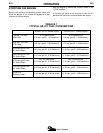
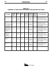
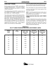
SIMULTANEOUS WELDING AND POWER
LOADS
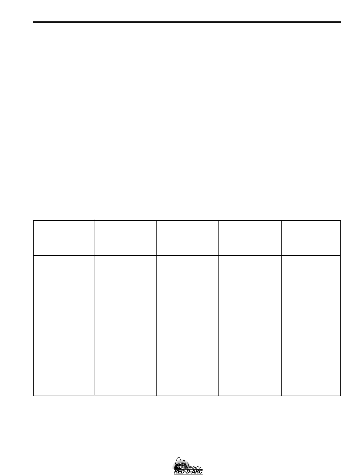
It must be noted that the above auxiliary power ratings
are with no welding load. Simultaneous welding and
power loads are specified in the following table. The
permissible currents shown assume that current is
being drawn from either the 120 VAC or 240 VAC
supply (not both at the same time).
Arc
Voltage
Welding
Output
Amps
Available Auxiliary
Power - Watts
(Unity Power
Factor)
Permissible
Auxiliary Current
in Amperes @
120V
Permissible
Auxiliary Current
in Amperes @
240V
33
31
26
20
14
7.5
4
0
66
62
52
40
28
15
8
0
8000
7400
6300
4800
3400
1800
1000
0
0
25
25
25
25
25
25
28
0
50
100
150
200
250
275
275
TABLE B.4
GX-271 SIMULTANEOUS WELDING AND POWER LOADS