


B-7
OPERATION
B-7
When the triggering device is pressed the contactor is
closed and the welding terminals are “Hot.”
When the triggering device is released the contactor is
opened and the welding terminals are “Cold.”
“MODE” Switch - Set to the desired process:
STICK/TIG, PIPE, or WIRE FEED.
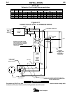
“WIRE FEEDER VOLTMETER” Switch - If
using a wire feeder that has a voltmeter, set this
switch to match the polarity of the electrode.
STICK WELDING
The GX-271 can be used with a broad range of DC
stick electrodes. The output “CONTROL” adjusts the
full range of 20 to 300 amps. Set the “ARC CON-
TROL” to low setting to minimize spatter. If sticking is
a problem, turn this control to a higher setting (clock-
wise). This will increase the short circuit current (arc
force).
PIPE WELDING
The “PIPE WELDING” mode is recommended for
manual vertical-down techniques on pipe joints using
EXX10 type electrodes. This slope controlled setting
allows the operator to control the welding current by
changing the arc length.
The “ARC CONTROL” (arc force) is automatically
switched off in this mode.
TIG WELDING
The GX-271 can be used in a wide variety of DC
Tungsten Inert Gas (TIG) welding applications. When
used with the K930-1 or -2 TIG module, ratings are
limited to 275A at a 60% duty cycle and 250A at a
80% duty cycle.
GX-271 settings when using the K930-1 or -2 Tig
Module:
a. Set the “MODE” Switch to the STICK/TIG setting.
b. Set the “IDLER” Switch to the “AUTO” position.
c. Set the “LOCAL/REMOTE” switch to the
“REMOTE” position.
d. Set the ”WELDING TERMINALS” switch to the
“WELDING TERMINALS REMOTELY CON-
TROLLED” position. This will keep the “Solid
State” contactor open and provide a “cold” elec-
trode until the triggering device (Amptrol or Arc
Start Switch) is pressed.
e. Set the “ARC CONTROL” to minimum.
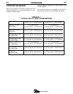
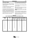
See Table B.2 for Typical Current Ranges for
Tungsten Electrodes.
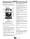
GX 271 Chopper