


GX 271 Chopper
B-6
OPERATION
B-6
purposes in each mode. It is not active in the “PIPE”
mode.
“STICK/TIG” mode: In this mode, the “ARC CON-
TROL” knob sets the short circuit (arc force) current
during stick welding. Increasing the number from 1 to
10 increases the short circuit current. This prevents
sticking of the electrode to the plate at low welding
current settings. This also increases spatter. It is rec-
ommended that the control is set to the minimum
number without electrode sticking.
“WIRE WELDING” mode: In this mode, increasing
the number from 1 to 10 changes the arc from soft
and washed in to crisp and narrow. It acts as an
inductance control. The proper setting depends on
the application and operator preference. In general,
Mig welding performs best in the “SOFT” range and
Innershield in the “CRISP” range.
“LOCAL” / “REMOTE” Switch
The toggle switch on the control panel labeled
“LOCAL/REMOTE” gives the operator the option of
controlling the output at the welder control panel or at
a wire feeder, TIG amptrol, or a K857 Remote Control
that is connected to either the 6 pin or 14 pin amphe-
nol connector.
For remote control the toggle switch is set in the
“REMOTE” position.
For control at the welder control panel, the toggle
switch is set in the “LOCAL” position.
“WELDING TERMINALS” Switch
The toggle switch on the control panel labeled
“WELDING TERMINALS ALWAYS ON” and “WELD-
ING TERMINALS REMOTELY CONTROLLED”, is
used to control the operation of the solid state contac-
tor which allows for the selection of “Hot” or “Cold”
welding terminals.
With the switch in the “WELDING TERMINALS
ALWAYS ON” position, the contactor is closed and
the welding terminals are always “Hot.”
With the switch in the “WELDING TERMINALS
REMOTELY CONTROLLED” position, the contactor
operation is controlled by an Amptrol, Arc Start Switch
or some other type of triggering device through the
use of a control cable connected to the 6 pin or 14 pin
amphenol.
WELDING OPERATION
WELDER CONTROLS - FUNCTION
AND OPERATION
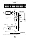
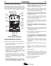
See Figure B.1 for control locations.
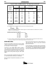
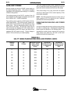
Output “CONTROL”
Continuous CC welding current control from 20 amps
to 300 amps in the STICK/TIG and PIPE modes.
Continuous CV welding arc voltage control from 11
volts to 32 volts in the WIRE FEED mode.
“ARC CONTROL”
The “ARC CONTROL” is active in two modes:
“STICK/TIG” and “WIRE WELDING” and has different
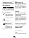
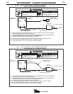
Do not attempt to use this equipment until you
have thoroughly read the engine manufacturer’s
manual supplied with your welder. It includes
important safety precautions, detailed engine
starting, operating and maintenance instructions,
and parts lists.
------------------------------------------------------------------------
ELECTRIC SHOCK can kill.
• Do not touch electrically live parts or
electrode with skin or wet clothing.
• Insulate yourself from work and
ground
• Always wear dry insulating gloves.
------------------------------------------------------------------------
FUMES AND GASES can be dangerous.
• Keep your head out of fumes.
• Use ventilation or exhaust to remove
fumes from breathing zone.
------------------------------------------------------------------------
MOVING PARTS can injure.
• Do not operate with doors open or
guards off.
• Stop engine before servicing.
• Keep away from moving parts.
------------------------------------------------------------------------
WELDING SPARKS can cause fire or
explosion.
• Keep flammable material away.
------------------------------------------------------------------------
ARC RAYS can burn.
• Wear eye, ear and body protection.
------------------------------------------------------------------------
See additional warning information
throughout this operator’s manual.
-----------------------------------------------------------
WARNING