


C>C8DGG:8IHE6G@6GG:HIDGB6NA:69ID96B6<:ID
I=::C<>C:DG69K:GH:AN6;;:8IE:G;DGB6C8:
------------------------------------------------------------------------
"#!" ,+/(3 !(,.),- ),
.#!**&#.#)(-
The K930-2 TIG Module is suitable for use with the
RANGER® 305LPG. The RANGER® 305LPG and
any high frequency generating equipment must be
properly grounded. See the K930-2 Operating Manual
for completed instructions on installation, operation,
and maintenance.
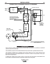
,').)(.,)&
The RANGER® 305LPG is equipped with a 6-pin and
a 14-pin connector. The 6-pin connector is for con-
necting the K857 or K857-1 Remote Control (optional)
or for TIG welding, the K870 foot Amptrol or the K963-
3 hand Amptrol.
When in the CC-STICK, PIPE, and CV-WIRE modes
and when a remote control is connected to the
Amphenol, the auto-sensing circuit in the RANGER®
305LPG automatically switches the OUTPUT control
from control at the welder to remote control.
The 14-pin connector is used to directly connect a
wire feeder or TIG Module (K930-2) control cable. In
the CV-WIRE mode, the RANGER® 305LPG auto-
sensing circuit automatically makes the RANGER®
305LPG Output Control inactive and the wire feeder
voltage control active when the control cable is con-
nected to the 14-pin connector.
().: When a wire feeder with a built in welding volt-
age control is connected to the 14-pin connector, do
not connect anything to the 6-pin connector.
&.,#&)((.#)(-
'"#(!,)/(#(!
Because this portable engine driven welder creates its
own power, it is not necessary to connect its frame to
an earth ground, unless the machine is connected to
premises wiring (home, shop, etc.) To prevent danger-
ous electric shock, other equipment to which this
engine driven welder supplies power must:
T:<GDJC9:9IDI=:;G6B:D;I=:L:A9:GJH>C<6
<GDJC9:9INE:EAJ<
T:9DJ7A:>CHJA6I:9DCDI<GDJC9I=:B68=>C:
ID6E>E:I=6I86GG>:H:MEADH>K:DG8DB7JHI>7A:
B6I:G>6A
------------------------------------------------------------------------
/.#)(
#(-.&&.#)(
,(!,U&*!
)#&
The RANGER® 305LPG is shipped with the engine
crankcase filled with high quality SAE 10W-30 oil.
Check the oil level before starting the engine. If it is
not up to the full mark on the dip stick, add oil as
required. Check the oil level every four hours of run-
ning time during the first 25 running hours. Refer to
the engine Operator’s Manual for specific oil recom-
mendations and break-in information. The oil change
interval is dependent on the quality of the oil and the
operating environment. Refer to the Engine Operator’s
Manual for the proper service and maintenance inter-
vals.
-------------------------------------------------------------------
(!#())&#(!-3-.'
Air to cool the engine is drawn in lower set of louvers
on the case back. It is important that the intake air is
not restricted. Allow a minimum clearance of 2 feet
(Im) from the case back to a vertical surface.
..,3)((.#)(
/H:86JI>DC6HI=::A:8IGDANI:>H6HIGDC<68>9I=6I
86C7JGCH@>C6C996B6<::N:H
------------------------------------------------------------------------
The RANGER® 305LPG is shipped with the negative
battery cable disconnected. Make certain that the
RUN-STOP switch is in the STOP position. Remove
the two screws from the rear battery tray using a
screwdriver or a 3/8" socket. Attach the negative bat-
tery cable to the negative battery terminal and tighten
using a 1/2" socket or wrench.
().: This machine is furnished with a wet charged
battery; if unused for several months, the battery may
require a booster charge. Be careful to charge the bat-
tery with the correct polarity.
'/ &,)/.&.*#*
Using the clamp provided secure the outlet pipe to the
outlet tube with the pipe positioned such that it will
direct the exhaust in the desired direction. Tighten
using a 9/16" socket or wrench.
-*,%,,-.,
Some federal, state or local laws may require that
gasoline or diesel engines be equipped with exhaust
spark arresters when they are operated in certain
locations where unarrested sparks may present a fire
hazard. The standard muffler included with this welder
does not qualify as a spark arrester. When required by
local regulations, a suitable spark arrester, such as the
K1898-1 must be installed and properly maintained.
1,(#(!
1,(#(!
/.#)(