


#(-.&&.#)(
,(!,&*!
)((.#)( ) &#()&( &.,#
1#, ,-
DCC:8I>DCD;&(DG&(IDI=:,(!,U
&*!
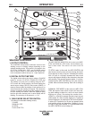
1. Shut the welder off.
2. Connect the LN-7 or LN-8 per instructions on the
appropriate connection diagram in Section F
3. Set the "WIRE FEEDER VOLTMETER" switch to
either "+" or "-" as required by the electrode being
used.
4. Set the "MODE" switch to the "CV WIRE " posi-
tion.
5. Set the "ARC CONTROL" knob to "0" initially and
adjust to suit.
6 Set the "WELD TERMINALS" switch to the
"REMOTELY CONTROLLED" position.
7. Set the "IDLE" switch to the "HIGH" position.
DCC:8I>DCD;&(IDI=:,(!,U&*!
These connections instructions apply to both the LN-
15 Across The-Arc and Control Cable models. The
LN-15 has an internal contactor and the electrode is
not energized until the gun trigger is closed. When the
gun trigger is closed the wire will begin to feed and the
welding process is started.
• Shut the welder off.
• For electrode Positive, connect the electrode cable
to the "+" terminal of the welder and work cable to
the "-" terminal of the welder. For electrode
Negative, connect the electrode cable "-" terminal of
the welder and work cable to the "+" terminal of the
welder.
T8GDHH.=:G8'D9:A
Attach the single lead from the front of the LN-15 to
work using the spring clip at the end of the lead. This
is a control lead to supply current to the wire feeder
motor; it does not carry welding current.
Set the "WELD TERMINALS" switch to "WELD TER-
MINALS ON"
TDCIGDA67A:'D9:A
Connect Control Cable between Engine Welder and
Feeder.
Set the "WELD TERMINALS" switch to "REMOTELY
CONTROLLED"
TSet the MODE switch to the "CV-WIRE " position.
TSet the "WIRE FEEDER VOLTMETER" switch to
either "+" or "-" as required by the electrode polarity
being used.
TSet the "ARC CONTROL" knob to "0" initially and
adjust to suit.
T Set the "IDLE" switch to the "AUTO" position.
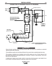
DCC:8I>DCD;I=:&(IDI=:,(!,U&*!
-=JID;;L:A9:G7:;DG:B6@>C<6CN:A:8IG>86A8DC
C:8I>DCH
------------------------------------------------------------------------
The LN-25 with or without an internal contactor may
be used with the RANGER® 305LPG. See the appro-
priate connection diagram in Section F.
().: The LN-25 (K431) Remote Control Module
and (K432) Remote Cable are not recommended for
use with the RANGER® 305LPG.
1. Shut the welder off.
2. For electrode Positive, connect the electrode
cable from the LN-25 to the "+" terminal of the
welder and work cable to the "-" terminal of the
welder. For electrode Negative, connect the elec-
trode cable from the LN-25 to the "-" terminal of
the welder and work cable to the "+" terminal of
the welder.
3. Attach the single lead from the front of the LN-25
to work using the spring clip at the end of the lead.
This is a control lead to supply current to the wire
feeder motor; it does not carry welding current.
4. Set the MODE switch to the "CV-WIRE " position.
5. Set the "WELD TERMINALS" switch to "WELD
TERMINALS ON"
6. Set the "ARC CONTROL" knob to "0" initially and
adjust to suit.
7. Set the "IDLE" switch to the "AUTO" position.
When not welding, the RANGER® 305LPG engine
will be at the low idle speed. If you are using an
LN-25 with an internal contactor, the electrode is
not energized until the gun trigger is closed.
8. When the gun trigger is closed, the current sensing
circuit will cause the RANGER® 305LPG engine to
go to the high idle speed, the wire will begin to feed
and the welding process started. When welding is
stopped, the engine will revert to low idle speed
after approximately 12 seconds unless welding is
resumed.
1,(#(!