


#(-.&&.#)(
,(!,U&*!
-.(3*)1,)((.#)(-
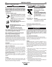
The RANGER® 305LPG is suitable for temporary, standby
or emergency power using the engine manufacturer’s rec-
ommended maintenance schedule.
The RANGER® 305LPG can be permanently installed as a
standby power unit for 240 VAC, 3 wire, single phase, 40
amp service. Connections must be made by a licensed elec-
trician who can determine how the 120/240 VAC power can
be adapted to the particular installation and comply with all
applicable electrical codes.
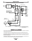
• Install the double-pole, double-throw switch between the
power company meter and the premises disconnect.
Switch rating must be the same or greater than the cus-
tomer’s premises disconnect and service over current pro-
tection.
• Take necessary steps to assure load is limited to the
capacity of the RANGER® 305LPG by installing a 40
amp, 240 VAC double pole circuit breaker. Maximum
rated load for each leg of the 240 VAC auxiliary is 40
amperes. Loading above the rated output will reduce out-
put voltage below the allowable - 10% of rated voltage
which may damage appliances or other motor-driven
equipment and may result in overheating of the
RANGER® 305LPG engine and/or alternator windings.
• Install a 50 amp, 120/240 VAC plug (NEMA Type 14-50)
to the double-pole circuit breaker using No. 6, 4 conductor
cable of the desired length. (The 50 amp, 120/240 VAC
plug is available in the optional K802R plug kit or as part
number T12153-9.)
• Plug this cable into the 50 Amp, 120/240 Volt receptacle
on the RANGER® 305LPG case front.
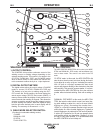
/2#&#,3*)1,,*.&-
Start the engine and set the “IDLER” control switch to
the “High Idle” mode. Voltage is now correct at the
receptacles for auxiliary power. This must be done
before a tripped GFCI receptacle can be reset proper-
ly. See the MAINTENANCE section for detailed infor-
mation on testing and resetting the GFCI receptacle.
The auxiliary power of the RANGER 305 LPG con-
sists of two 20 Amp-120 VAC GFCI (5-20R) duplex
receptacles and one 50 Amp 120/240 VAC (14-50R)
receptacle. The 240 VAC receptacle can be split for
single phase 120 VAC operation.
The auxiliary power capacity is 9,000 Watts Peak,
8000 Watts Continuous of 60 Hz, single phase power.
The auxiliary power capacity rating in watts is equiva-
lent to volt-amperes at unity power factor. The max
permissible current of the 240 VAC output is 33 Amps.
The 240 VAC output can be split to provide two sepa-
rate 120 VAC outputs with a max permissible current
of 33 Amps per output to two separate 120 VAC
branch circuits (these circuits cannot be paralleled).
Output voltage is within ± 10% at all loads up to rated
capacity. All auxiliary power is protected by circuit
breakers.
The 120 V auxiliary power receptacles should only be used
with three wire grounded type plugs or approved double
insulated tools with two wire plugs. The current rating of any
plug used with the system must be at least equal to the cur-
rent capacity of the associated receptacle.
(). The 240 V receptacle has two 120 V circuits, but
are of opposite polarities and cannot be paralleled.