


*-!'.%$,'$##)$#(
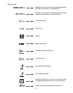
The power source is equipped to furnish nominally
115 volt AC and 42 volt AC auxiliary power for operat-
ing wire feeding equipment, etc. The auxiliary power
is available at the 14-pin MS-style connector recepta-
cle on the control panel and/or at a terminal strip
behind the hinged control panel on the front of the
power source. 115V AC is available at receptacle
pins A and J, (except on European model), and termi-
nals 31 and 32. 42V AC is available only at recepta-
cle pins I and K. The 115V AC and the 42V AC are
isolated circuits and each is protected by a 10 amp
circuit breaker.
'"$)$#)'$!$##)$#(
Remote control connections are available both at a
14-pin connector receptacle located on the control
panel, and on terminal strips with screw connections
located behind the hinged control panel on the front of
the power source.
,)'R$$!'R$##)$'
A Continental European receptacle (220V Schuko
type) is located on the rear panel for supplying
220VAC to a water cooler. A 2 amp circuit breaker
which is also located on the rear panel protects this
circuit.
$*)%*)$##)$#(
The output terminals are recessed on the case front
and labeled “
” and “”. The CV 500-I provides Twist-
Mate™ European connector receptacles.
K852 Twist-Mate European connector plugs are avail-
able for the cable size to be used. The Export model
includes two Twist-Mate plugs for 2/0 - 3/0 (70-
95mm
2
) cable and S18737 installation instructions.
#%*)$##)$#(
The three input lines are brought in through the rear
panel of the power source and attached to the input
contactor. Removal of the removable access panel
makes the contactor accessible for the input cable
connections.
#%*)!#+$!)$"%#()$#
The power source is equipped with input line voltage
compensation as standard. For a line voltage fluctua-
tion of ±10% the output will remain essentially con-
stant. This is accomplished through the feedback net-
work in the control circuit.
($!())$*)%*)$#)'$!
The output of the welder is electronically controlled by
SCR’s instead of mechanical contactors, providing
extra long life for highly repetitive welding applica-
tions.
($!())$#)'$!(.()"
The Control PC Board is located behind the control
panel which hinges down for easy access to the
board. The Snubber PC Board is mounted on the
back of the case front.
"#$$!#
The fan pulls air in through the louvered front of the
machine over the internal parts and exhausts out the
louvered rear of the machine. The fan motor is fully
enclosed, has sealed ball bearings, requires no lubri-
cation, and operates when the power switch is turned
on.
()*'(
The machine uses a 32” (813mm) long base. The low
profile case facilitates installation of the machine
under a workbench and stacking the machines three
high to conserve floor space.
The case front incorporates a recessed hinged control
panel where all the machine controls are mounted.
This recessed panel protects the controls and mini-
mizes the possibilities of accidental contact. This con-
trol panel can be easily opened to permit access to
the enclosed section which contains the terminal
strips, PC board, etc.The output lead terminals are
also recessed to avoid any object or person acciden-
tally coming in contact with an output terminal.
The individual case sides are removable for easy
access for internal service or inspection. These are
removable even though the machines are stacked
three high.
The case rear, top section, is equipped with a remov-
able access panel. This provides easy access to the
input contactor, easy connection and reconnection of
input leads, and easy access for service or inspection.
Although the machine is designed for use in rain-sheltered
environemnts, the transformer and choke assembly
are dipped in a special corrosion resistant epoxy
paint.
A permanent lifting hook is located at the top of the
machine and is positioned so that it acts as nearly as
possible through the center of gravity. This lift hook is
so positioned that it fits without interference under the
base of the second machine when stacking.
– 13 –