


.800
.385
.415
.167
.207
.503
.513
.150
.200
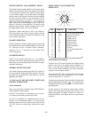
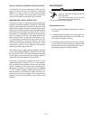
BRASS
.600
.553
TIN PLATED
COPPER TUBE
.740
N.B.
N.A.
NOTES:
N.A. DISPLACEMENT HOLE PERMISSIBLE.
RUBBER BOOT
MARKED WITH
"70-95"
(2)SET SCREWS
RAISED TAB NOT IMPORTANT.
N.B. RELATIONSHIP BETWEEN SET SCREWS AND
M15479-1
9-20-91J
.800
.385
.415
.167
.207
.503
.513
.150
.200
BRASS
.600
.553
TIN PLATED
COPPER TUBE
.740
N.B.
N.A.
NOTES:
N.A. DISPLACEMENT HOLE PERMISSIBLE.
RUBBER BOOT
MARKED WITH
"70-95"
(2)SET SCREWS
RAISED TAB NOT IMPORTANT.
N.B. RELATIONSHIP BETWEEN SET SCREWS AND
M15479-1
9-20-91J
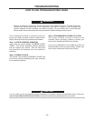
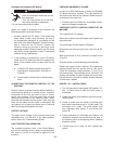
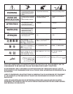
TURN THE POWER SWITCH OF THE WELDING POWER
SOURCE "OFF" BEFORE INSTALLING PLUGS ON CABLES
OR WHEN CONNECTING OR DISCONNECTING PLUGS TO
WELDING POWER SOURCE.
1.
WELDING CABLE
BOOT
TRIM
Slide the copper tube into the brass plug.
Insert cable into copper tube.
COPPER TUBE
Slide rubber boot over brass plug. The rubber boot must be
p
ositioned to completely cover all electrical surfaces after
the plug is locked into the receptacle.
SET SCREW
B
RASS PLUG
BOOT MARKING
2
2
5
0-70
70-95
C
ABLE SIZE
1
/0-2/0
CABLE SKIN LENGTH
1 INCH (25.4mm)
2
.
2/0-3/0
50-70
70-95
mm )
m
m )
(
(
AMERICAN (EUROPEAN) RANGE
CHECK THAT THE CONNECTOR BOOT IS MARKED FOR THE
APPROPRIATE CABLE SIZE PER TABLE BELOW; AND
S
KIN CABLE JACKET TO LENGTH SPECIFIED:
1 INCH (25.4mm)
35-50
2
mm )
(
35-50
#2-#1
TWIST-MATE WELDING CABLE PLUG INSTALLATION INSTRUCTIONS
1.5 INCH (38.1mm)
must apply firm pressure against welding cable. The top of the
(
70-95 size may
have 2 set
screws)
SEE
A
BOVE
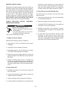
Tighten set screw(s) to collapse copper tube. Screw(s)
brass plug after tightening.
set screw(s) will be nearly flush or below the surface of the
7.
6.
5.
4.
3.
Slide rubber boot onto cable end.
If necessary, trim cable end of boot at groove(s) to match cable
d
iameter. Boot must fit tightly enough to seal around outside
different cable diameters without trimming. These boots do not
based lubricant will help to slide the boot over the cable.
h
ave grooves at the cable end. Soap or other non petroleum
d
iameter of cable. NOTE: Some boots are designed to accommodate
S18737
9-20-91J
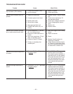
TURN THE POWER SWITCH OF THE WELDING POWER
SOURCE "OFF" BEFORE INSTALLING PLUGS ON CABLES
OR WHEN CONNECTING OR DISCONNECTING PLUGS TO
WELDING POWER SOURCE.
1.
WELDING CABLE
BOOT
TRIM
Slide the copper tube into the brass plug.
Insert cable into copper tube.
COPPER TUBE
Slide rubber boot over brass plug. The rubber boot must be
p
ositioned to completely cover all electrical surfaces after
the plug is locked into the receptacle.
SET SCREW
B
RASS PLUG
BOOT MARKING
2
2
5
0-70
70-95
C
ABLE SIZE
1
/0-2/0
CABLE SKIN LENGTH
1 INCH (25.4mm)
2
.
2/0-3/0
50-70
70-95
mm )
m
m )
(
(
AMERICAN (EUROPEAN) RANGE
CHECK THAT THE CONNECTOR BOOT IS MARKED FOR THE
APPROPRIATE CABLE SIZE PER TABLE BELOW; AND
S
KIN CABLE JACKET TO LENGTH SPECIFIED:
1 INCH (25.4mm)
35-50
2
mm )
(
35-50
#2-#1
TWIST-MATE WELDING CABLE PLUG INSTALLATION INSTRUCTIONS
1.5 INCH (38.1mm)
must apply firm pressure against welding cable. The top of the
(
70-95 size may
have 2 set
screws)
SEE
A
BOVE
Tighten set screw(s) to collapse copper tube. Screw(s)
brass plug after tightening.
set screw(s) will be nearly flush or below the surface of the
7.
6.
5.
4.
3.
Slide rubber boot onto cable end.
If necessary, trim cable end of boot at groove(s) to match cable
d
iameter. Boot must fit tightly enough to seal around outside
different cable diameters without trimming. These boots do not
based lubricant will help to slide the boot over the cable.
h
ave grooves at the cable end. Soap or other non petroleum
d
iameter of cable. NOTE: Some boots are designed to accommodate
S18737
9-20-91J
– 28 –