


– 17 –
Failure to follow these instructions can cause immedi-
ate failure of components within the machine.
When powering welder from a generator be sure to
turn off the welder first, before generator is shut down
in order to prevent damage to welder.
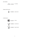
$CB>CB01:4=<<42B8=<A
The output leads are connected to the output termi-
nals marked “
” and “”.
They are located at the lower
right and lower left corners of the front panel. The
CV
500-I provides Twist-Mate European weld cable con-
nector receptacles.
K852 Twist-Mate European connector plugs are avail-
able for the cable size to be used. The Export model
includes two Twist-Mate plugs for 2/0 - 3/0 (70-95mm2)
cable and S18737 installation instructions. This informa-
tion is also located at the rear of this manual.
$CB>CB01:4A
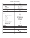
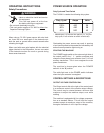
!(/($'$"#!#)$
!)'$#,$' !
*).
.!
*).
.!
"#!$
!!#)(
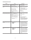
UP TO 50 ft
(15m)
50 to 100 ft
(15-30 m)
100-150 ft
(30-46 m)
150-200 ft
(46-61 m)
200-250 ft
(67-76 m)
3/0
85 mm
2
3/0
85 mm
2
3/0
85 mm
2
3/0
85 mm
2
4/0
107 mm
2
2/0
67 mm
2
2/0
67 mm
2
3/0
85 mm
2
3/0
85 mm
2
4/0
107 mm
2
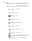
<AB0::0B8=<=584:3<AB0::43$>B8=<A
'"$)$*)%*)$#)'$!
,) %)'$'
The K857 has a 6-pin MS-style connector. The K857
requires a K864 adapter cable which connects to the
14-pin connector on the machine.
The K775 consists of a control box with 28 ft (8.5m) of
four conductor cable. This connects to terminals 75, 76,
and 77 on the terminal strip and the case grounding
screw so marked with the symbol on the machine.
These terminals are located behind the control panel on
the front of the power source. This control will give the
same control as the output control on the
machine.
'"$)$#)'$!%)'!
A “V” cable 12” (.30m) long to connect a K857
Remote Control (6 pin connector) with a wire-feeder
(14-pin connector) and the machine (14-pin connec-
tor). If a remote control is used alone the wire-feeder
connection is then not used.
%)$'(''*)
Circuit that mounts inside the CV 500-I.
Recommended when:
1) CV 500-I is used in conjunction with any LN-23P or
older LN-8 or LN-9 semiautomatic wire-feeder.
Eliminates possible arc flash re-start of weld when
trigger interlock is used. Not required with current
LN-8 (above Code 8700), or LN-9’s with serial
numbers above 115187 (manufactured after
12/83), or any LN-9 having an L6043-1 Power PC
Board.
2) CV 500-I is used with an LN-22 equipped with an
older K279 Contactor-Voltage Control Option.
Eliminates electrode overrun when gun trigger is
released. Not required when later K279 (above
Code 8800) is used.
3) CV 500-I is used with any semiautomatic wire-
feeder and possible small spark, if electrode touch-
es work just after gun trigger is released, is objec-
tionable.
Install per M17060 instructions included with the
Kit.
!)'($ 20<98::
MTurn the power switch of the
welding power source “$”
before installing plugs on cables or
when connecting or disconnecting plugs to
welding power source.
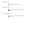
------------------------------------------------------------
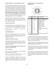
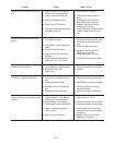
,'##
S
TRAIGHT PLUG (14 PIN)
TO POWER SOURCE
CABLE RECEPTACLE (6 SOCKET)
CABLE RECEPTACLE (14 SOCKET)
T
O: K857 REMOTE CONTROL
TO: LN-7 WIRE FEEDERS
S
TRAIGHT PLUG (14 PIN)
TO POWER SOURCE
CABLE RECEPTACLE (6 SOCKET)
CABLE RECEPTACLE (14 SOCKET)
T
O: K857 REMOTE CONTROL
TO: LN-7 WIRE FEEDERS
CAUTION