


– 18 –
*#'''( %
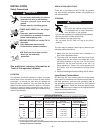
For easy moving of the machine, optional undercar-
riages are available with polyolefin wheels (K817P) or
a platform undercarriage (K841) with mountings for
two gas cylinders at rear of welder.
Install per instructions provided with undercarriage.
<AB0::0B8=< =5?C8>;4<B '4?C8@43 5=@
'42=;;4<343%@=24AA4A
,''$#)'$!!$##)$#(
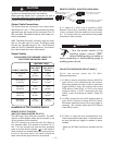
For control cable with 14-pin connector:
Connect control cable to 14-pin connector on the front
panel of the machine. See the appropriate connection
diagram for the exact instructions for the wire feeder
being used. Refer to “115VAC and 42VAC Auxiliary
Power and Control Connections” section for connector
pin functions.
A cover (Lincoln Electric Part Number S17062-3) is
available for the unused 14-pin connector to protect it
against dirt and moisture.
For control cable with terminal strip connectors:
The control cable from the wire feeding equipment is
connected to the terminal strips behind the control
panel. A strain relief box connector is provided for
access into the terminal strip section. A chassis
ground screw is also provided below the terminal strip
marked with the symbol for connecting the auto-
matic equipment grounding wire. See the appropriate
connection diagram for the exact instructions for the
wire feeder being used. Refer to “115VAC and 42VAC
Auxiliary Power and Control Connections” section for
access to terminal strips.
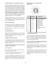
$##)$#$+)$!#$'!#
a) Turn off all power.
b) Connect a jumper from “2 to 4” on terminal strip
TS2 or jumper pins “C to D” in 14-pin connector
plug ( a K484 14-pin jumper plug is available).
c) Connect the electrode cable to the output terminal
of polarity required by electrode. Connect the work
lead to the other terminal.
d) Place the OUTPUT CONTROL Switch at “LOCAL”
position unless a Remote Control is connected to
the CV 500-I.
#$) The output terminals are energized at all
times.