


– 20 –
$*)%*)$#)'$!O!$!'"$)P(,)
The Output Control toggle switch on the control panel
labeled “Local-Remote” gives the operator the option
of controlling the output at the machine control panel
or at a remote station. For remote control, the toggle
switch is set in the “Remote” position and controlled at
the wire feed unit control, or by connecting a K775
control to terminals 75, 76, and 77 on the terminal
strip at the front of the machine, or by connecting a
K857 control with a K864 adapter to the 14-pin con-
nector on the front of the machine. For control at the
machine control panel (Output Voltage control dial),
the toggle switch is set in the “Local” position.
(Exception: When used with an LN-9, LN-9 GMA or
NA-5 wire feeder, the Output Control switch must be
in the “Remote” position or automatic shutdown of the
LN-9 or NA-5 may occur.)
%$!').(!)$#
Polarity selection is made by appropriately connecting
the electrode and work welding cables to either the
“
” terminal or to the “” terminal. Select “Voltmeter”
switch for “
” or “” electrode for the remote (#21)
work sensing lead.
+$!)")'(,)
Select “
” for positive electrode or “” for negative
electrode. This switch selects electrode polarity for the
remote (#21) work sensing lead of automatic or semi-
automatic equipment.
)'"!%'$))$#!)
The amber thermal protection light will be lit if either of
the two protective thermostats have opened. The out-
put power will be disabled but input power will still be
applied to the welder.
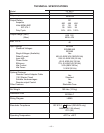
+R0<3+R*-!'.%$,'#
$#)'$!$##)$#(
%8<=<<42B=@
The 14-pin connector receptacle (type MS-3102A-20-
27SX) supplies auxiliary power.
42 VAC is available at receptacle pins I and K.
A 10 amp circuit breaker protects this circuit.
115 VAC is available at receptacle pins A and J
(except on the European model). A 10 amp circuit
breaker protects this circuit. Note that the 42 VAC and
115 VAC circuits are electrically isolated from each
other.
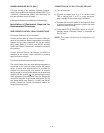
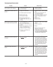
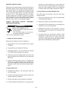
'$#)+,$%#$##)$'
'%)!
%# !R#$ *#)$#
A 32
115 VAC (Export Model Only)
B GND Chassis Connection
C2 Trigger Circuit
D4 Trigger Circuit
E 77 Output Control
F 76 Output Control
G 75 Output Control
H 21 Work Connection
I 41 42 VAC
J 31
115 VAC (Export Model Only)
K 42 42 VAC
L --- ---
M --- ---
N --- ---
F
=76
G=75
H=21
I=41
J
=31
K
=42
A=32
B=GND
C=2
D=4
E=77
LN
M
F
=76
G=75
H=21
I=41
J
=31
K
=42
A=32
B=GND
C=2
D=4
E=77
LN
M
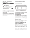
)4@;8<0:(B@8>=<<42B8=<A
Terminal strip TS2 located behind the hinged control
panel on the front of the power source supplies 115
VAC. A 10 amp circuit breaker protects this circuit.
This 115 VAC is also available in the 14-pin connector
(except on the European model).
Terminal strip TS1 also located behind the hinged
control panel allows for connecting of a K775 remote
control to terminals 75, 76, and 77.
A chassis ground screw is provided below the terminal
strips marked with the symbol for connecting the
automatic equipment grounding wire or remote control
grounding wire.
To gain access to the terminal strips simply remove
the two #10 sheet metal screws from the top of the
welder nameplate. Tilt panel forward so it rests in a
horizontal position. See Table above for lead number
functions.