


– 27 –
'"$)$#)'$!
Disconnect the remote output control and connect an
ohmmeter across 75 and 76 and rotate the rheostat in
the remote control. The resistance reading should go
from zero to 10K ohms. Repeat with ohmmeter across
77 and 76 with same results. Connect ohmmeter
across 75 and 77. The reading should be 10K ohms.
A lower reading will indicate a shorted or partially
shorted rheostat. A very high reading will indicate an
open rheostat. In either of the last two cases, replace
rheostat. Check cable for any physical damage.
%$,' ')' ' (("!.
#%'$*'
@83640<34D824A=:0B8=<
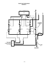
Disconnect the following, shown in Diagram 1:
a. Unplug P3 (G1, G2, G3, and 204) from the Control
PC Board.
b. Unplug P5 from the Snubber PC Board.
c. Secondary leads X1, X2, and X3 from the anodes
of the SCR’s and cathodes of the diodes.
d. Disconnect positive bridge lead from shunt and
positive capacitor bank lead and from lug with dual
204 leads.
e. Perform following steps 2 and 3. If diodes and
SCR’s are not shorted, bridge test is completed. If
any device appears shorted, disconnect the cath-
ode lead of each diode (4 total) and repeat steps 2
and 3.
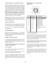
%=E4@8=34)4AB
a. Establish the polarity of the ohmmeter leads and
set to X10 scale.
b. Connect the ohmmeter positive lead to anode and
negative lead to the cathode.
c. Reverse the leads of the ohmmeter from Step b.
d. A shorted diode will indicate zero or an equally low
resistance in both directions. An open diode will
have an infinite or high resistance in both direc-
tions and a good diode will have a low resistance
in Step b. and a much higher resistance in Step c.
%=E4@(8:82=<=<B@=::43'42B8584@)4AB
The SCR must be mounted in the heat sink when
making this test.
a. Connect the ohmmeter (set to the X10 scale) leads
to the anode and cathode.
b. Reverse the leads of the ohmmeter from Step a.
c. A shorted SCR will indicate zero or an equally low
resistance in one or both directions.
d. Establish the polarity of the ohmmeter. Connect
the positive lead to the gate and the negative lead
to the cathode.
e. An open gate circuit will have an infinite or high
resistance. A good gate circuit will read a low
resistance, but not zero ohms. If gate circuit reads
zero ohms, check gate harness for shorts between
gate leads and 204 before replacing SCR.
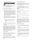
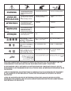
!)'R($ can kill.
• Have an electrician install and service
this equipment.
• Turn the input power off at the fuse
box before working on equipment.
• Do not touch electrically hot parts.
---------------------------------------------------------------------
,'##