


INSTALLATION
– 3 –
TIG MODULE
6. Keep all access panels and covers securely in
place.
7. All electrical conductors within 50 feet (15.2 m) of
the welder should be enclosed in grounded rigid
metallic conduit or equivalent shielding. Flexible
helically-wrapped metallic conduit is generally not
suitable.
8. When the welder is enclosed in a metal building,
several good earth driven electrical grounds (as in
5 (b)) around the periphery of the building are
recommended.
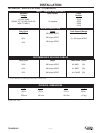
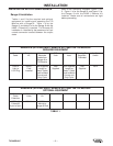
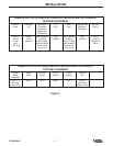
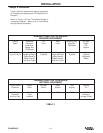
SUPPLY CONNECTIONS
Control cables are needed to connect the TIG
Module’s 9-pin Input Receptacle to the power source.
Four different cables are available. The proper choice
of cable depends on the power source being used.
Included in this report are charts which specify which
cable is used with a particular power source. The
cables come in standard 5 ft.(1.5m) lengths. 22(6.7m)
and 45(13.7) ft. extensions are available.
Input power should be nominally 115 volts AC, but the
TIG Module will operate properly on any AC voltage
from 60 to 130 volts, 50 or 60 Hz. Input current draw
is 1.3 amps at 115 volts.
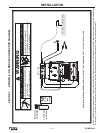
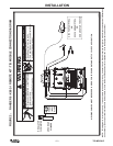
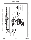
INPUT AND OUTPUT CONNECTIONS
Input Connections
The user must provide welding cables for the
connections between the work and electrode
terminals of the power source, and the “FROM
POWER SOURCE WORK” and “FROM POWER
SOURCE ELECTRODE” terminals of the TIG
Module. All connections are made with 1/2-13
threaded stud output terminals. Choose cables
according to the output currents and duty cycles
listed below.
200 Amps 100% Duty Cycle #2 AWG(30mm
2
)
(minimum) Cable
300 Amps 60% Duty Cycle #1 AWG(35mm
2
)
(minimum) Cable
400 Amps 20% Duty Cycle #1/0 AWG(50mm
2
)
(minimum) Cable
These ratings are for cables lengths of 150
ft.(46.0m) or less.
Note that two of the studs are labeled “FROM
POWER SOURCE”; these are to be connected to
the power source work and electrode terminals. If
the power source output terminals are not labeled
“WORK” and “ELECTRODE”, the TIG Module
“FROM POWER SOURCE ELECTRODE”
terminal should go to the power source output
terminal which matches the desired welding
polarity. This is the negative (-) terminal when
welding DC-. The choice of power source
terminal will have no effect when welding AC.
TIG Torch and Workpiece Connections
One terminal is labeled “TO TIG TORCH”. Use
that terminal for the TIG torch connection. TIG
torches come in 12.5ft.(3.8m) and 25ft.(7.6m)
lengths; use the shorter size whenever possible to
minimize the possibility of high frequency
interference.
The last terminal is labeled “TO WORKPIECE”.
Use short lengths whenever possible to minimize
the possibility of high frequency interference.
Shielding Gas Connections
The gas valve connections are labeled “GAS
INPUT” and “GAS OUTPUT”. Any torch and gas
supply conforming to Compressed Gas
Association (CGA) standards can be connected
via the 5/8-18 right hand threaded fittings. The
cylinder of shielding gas must be equipped with a
regulator and flowmeter. Install a hose between
the flowmeter and the input fitting.
Water Valve Connection
The optional K844-1 Water Valve Kit can be
installed in the TIG Module to provide on/off flow
control for cooling water. The water valve opens
and closes at the same time as the gas valve, so
cooling water flows during the afterflow period.
Connections are made via the two 5/8-18 left
hand threaded connections. If using a water-
cooled torch with a free running water supply,
install a water line between the water supply and
the “WATER INPUT” fitting on the TIG Module.
Include a strainer in the supply line to prevent dirt
particles from obstructing the water flow in the
valve and cooling chamber of the TIG torch.
Failure to do so could result in overheating of the
water-cooled torch. Connect the torch water line
to the “WATER OUTPUT” fitting. Use a
nonmetallic drain line from the TIG torch power
block to the drain.