


INSTALLATION WITH A POWER SOURCE
Ranger 8 Installation
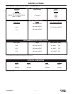
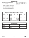
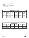
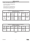
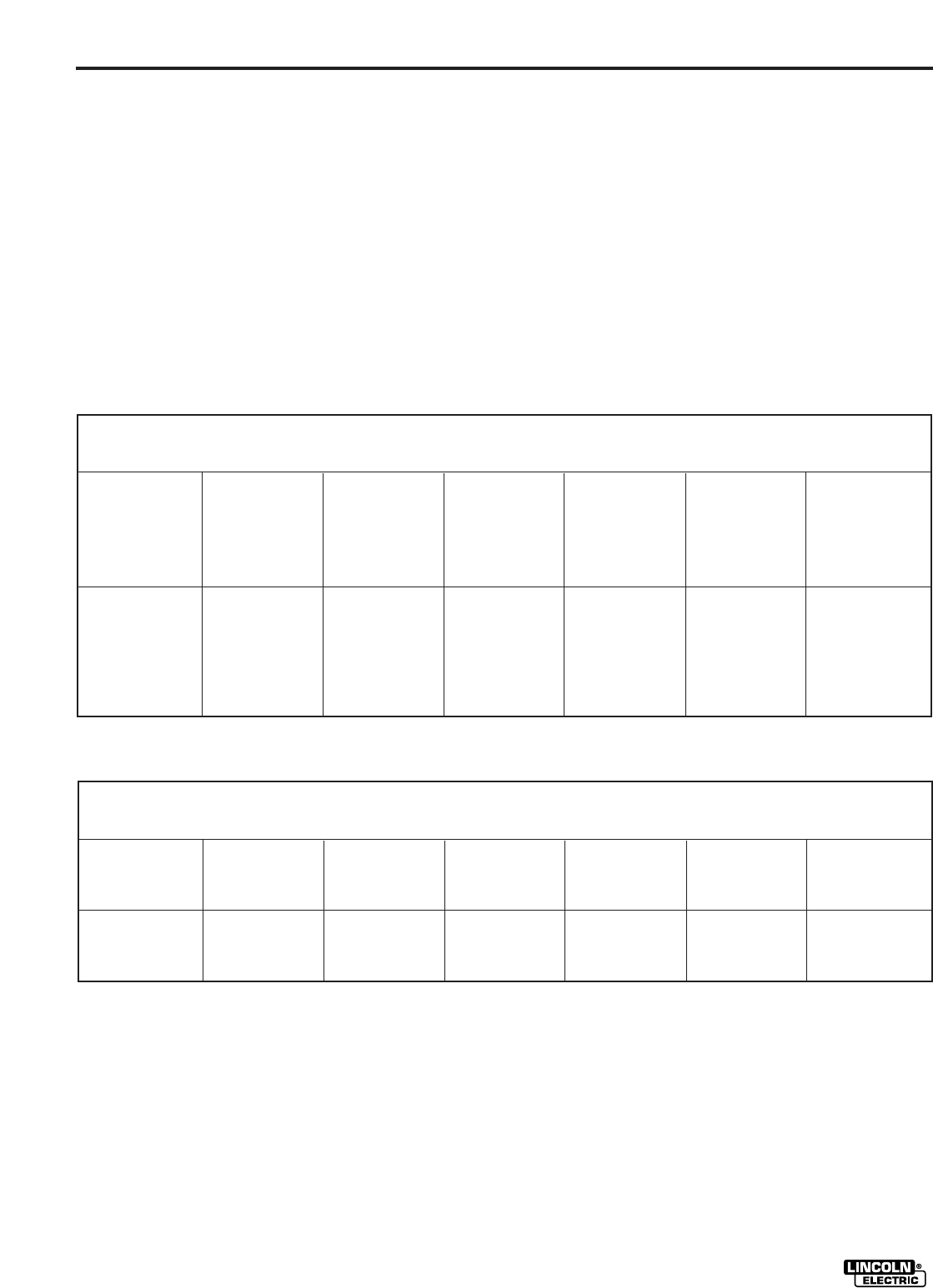
Tables 1 and 2 list the required and optional
equipment for installing and operating the TIG
Module with a Ranger 8. Table 1 is for the
Ranger 8, and table 2 is for the Ranger 8 with the
K892-1 Remote Kit installed. The Remote Kit
installation is identified by the presence of a 6-pin
remote connector located between the output
studs.
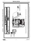
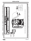
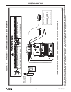
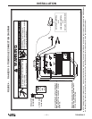
Refer to the Connection Diagrams Figures 1 and
2. Figure 1 is for the Ranger 8, and figure 2, for
the Ranger 8 with the K892-1 Remote Kit
installed. Make sure all connections are tight
before proceeding.
INSTALLATION
– 5 –
TIG MODULE
RANGER 8 (WITH NO K892-1 REMOTE KIT) AND THE TIG MODULE
REQUIRED EQUIPMENT
Control
Cable
Contactor
Kit
Work and
Electrode
Leads from
Ranger 8 to
TIG Module
TIG
Torch
Work
Lead
Shielding Gas,
Regulator,
Flowmeter
Arc Start
Switch
K936-4
9-pin to
115V Plug
K938-1
Field
Installed
User Supplied;
Length as
Req’d. Cable
Sized to Match
Current and
Duty Cycle
User
Supplied
User Supplied;
Length as
Req’d. Cable
Sized to Match
Current and
Duty Cycle
User
Supplied
K814
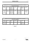
RANGER 8 (WITH NO K892-1 REMOTE KIT) AND THE TIG MODULE
OPTIONAL EQUIPMENT
Control
Cable
Extension
Water
Valve
Docking
Kit
K937 - [ ]
Extension
9-pin to 9-pin
K844-1 K939-1
Mounts to
Ranger 8 Roof
TABLE 1