


OPERATION
– 22 –
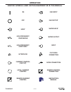
WARNING
ELECTRODE
WORK
V
1
2
3
44
5
6
7
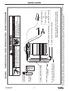
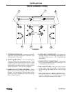
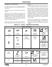
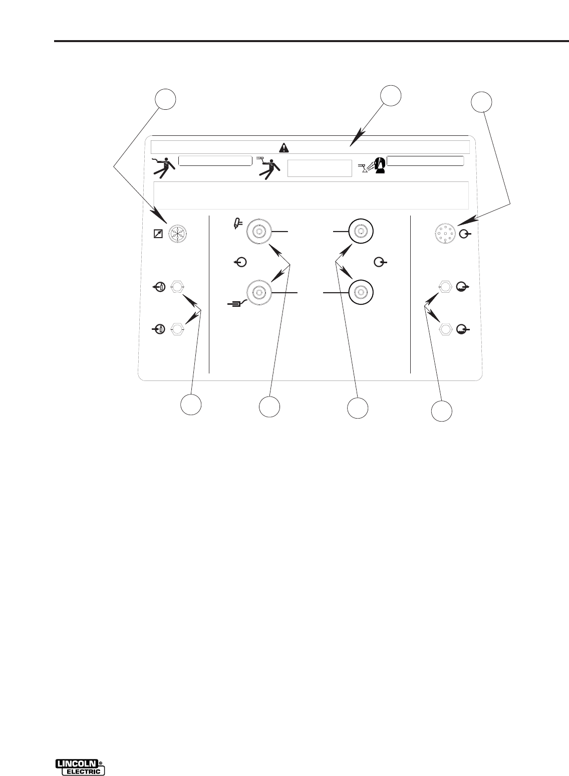
REAR CONNECTIONS
FIGURE 8
1 WARNING INFORMATION - Important information
regarding the safe installation, operation, and
servicing of the TIG Module.
2 INPUT RECEPTACLE - For connecting the
Control Cable from the power source. This
receptacle contains the following circuits: Input
power, power source contactor control (where
applicable) and power source remote control
(where applicable). This is a 9-pin receptacle.
3 WATER VALVE FITTINGS (OPTIONAL) - Water
valve inlet and outlet fittings, 5/8-18 left-hand
threads. For connection of cooling water to and
from the TIG torch. Supplied as part of the optional
K844-1 Water Valve Kit.
4 POWER INPUT CONNECTIONS - Connections for
the work (bottom) and electrode (top) cables from
the Ranger power source. 1/2-13 threaded stud
connections.
5 POWER OUTPUT CONNECTIONS - Connections
for the work lead (bottom) and TIG torch (top). 1/2-
13 threaded stud connections.
6 GAS VALVE FITTINGS - Gas valve inlet and outlet
fittings, 5/8-18 right hand threads. For connection
of the shielding gas supply and the TIG torch gas
fitting.
7 ARC START SWITCH / AMPTROL RECEPTACLE -
6-socket receptacle for connecting an arc start
switch or an Amptrol remote current control.
TIG MODULE