


A-3
INSTALLATION
PRO-CUT 80
A-3
INPUT ELECTRICAL
CONNECTIONS
Before installing the machine, check that input supply
voltage, phase, and frequency are the same as the
machine's voltage, phase, and frequency as specified
on the machine's rating plate.
The Pro-Cut 80 should be connected only by a quali-
fied electrician. Installation should be made in accor-
dance with all local and national codes (eg: U.S.
National Electrical Code) and the information detailed
below.
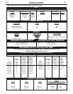
THREE PHASE POWER INPUT CONNEC-
TION FOR THE PRO-CUT 80
The Pro-Cut 80’s are supplied with one 10 ft. #8 AWG
4-conductor input power cord already connected to
the machine. When received from the factory, the
machine is internally connected for the higher input
voltage. Re-connection will be necessary if a lower
input voltage is used.
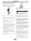
CONVERTING THE PRO-CUT 80 FROM
THREE PHASE TO SINGLE PHASE INPUT
To convert to single phase power, the 4-conductor
input cord may still be used, but the red lead must be
disconnected and insulated.
1. Connect the green lead to ground per U.S. National
Electrical Code.
2. Connect black and white leads to power.
3. Wrap red lead with tape to provide 600V insulation.
Machine damage could result if the machine is
improperly configured for the Input Voltage
applied.
------------------------------------------------------------------------
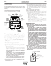
INPUT POWER CORD CONNECTOR
INSTALLATION
A cord connector provides a strain relief for the input
power cord as it passes through the left rear access
hole. The cord connector is designed for a cord diam-
eter of .40 - 1.03 in (10.2 - 26.2mm) if it becomes nec-
essary to install a different input cord.
CORD REMOVAL:
1. Unplug line cord from the receptacle.
NOTE: DO NOT PERFORM THE NEXT STEP
UNTIL THE HIGH VOLTAGES INSIDE THE
MACHINE HAVE BEEN ALLOWED TO DISSIPATE,
APPROXIMATELY TWO MINUTES.
------------------------------------------------------------------------
2. Remove wraparound by unscrewing the eleven
screws on the case sides and top.
3. Unscrew the four screws that hold the line switch
onto the case front.
4. Pull the line switch out of the case front.
5. Angle the line switch so the nuts on the switch can
be loosened.
6. Remove the cord from the switch.
7. Remove the nut, lock washer, plain washer and
green lead off of the ground screw assembly.
8. Loosen the cable connector on the case back.
9. Pull the line cord out of the machine.
CORD INSTALLATION:
1. Feed the new cord through the cable connector
and into the machine.
2. If the ground screw assembly is loose, tighten the
assembly to the base before installing the new
ground lead. Install the green lead on the ground
screw assembly, replace the plain washer and lock
washer, then tighten nut. Install in accordance with
all local and national electrical codes.
3. Connect the new cord to the switch, observing the
color code on the wiring diagram.
4. Feed the line switch back into case front.
5. Replace the four screws that hold the line switch
onto the case front.
6. Tighten the cable connector on the case back.
7. Replace wraparound and tighten the eleven
screws on the case sides and top.
8. Connect the new input power cord to a fused three
phase power supply. Make sure the green lead is
connected to the panel and the panel is connected
to a good earth ground. Install in accordance with
all local and national electric codes.
NOTE: Fusing requirements of the machine input will
change, depending on whether the machine is used
on single phase or three phase. Use the chart in the
TECHNICAL SPECIFICATIONS to change the fuses
to the proper value.
WARNING
WARNING