


B-7
OPERATION
B-7
Suggestions for Extra Utility from the
PRO-CUT System:
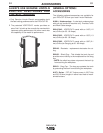
1. Occasionally an oxide layer may form over the tip
of the electrode, creating an insulating barrier
between the electrode and nozzle. This will result
in the tripping of the Pro-Cut's safety circuit. When
this happens turn the power off, remove the nozzle
and electrode and use the electrode to rub against
the inside bottom surface of the nozzle. This will
help remove any oxide buildup. If the Parts-in-
Place circuit continues to trip after cleaning the
consumables, then replace them with a new set.
Do not continue to try and cut with excessively
worn consumables as this can cause damage to
the torch head and will degrade cut quality.
2. To improve consumable life, here are some sug-
gestions that may be useful:
a. Never drag the nozzle on the work surface if
the output control knob is set above 45 Amps.
b. Make sure the air supply to the Pro-Cut is
clean and free of oil. Use several extra in line
filters if necessary.
c. Use the lowest output setting possible to make
a good quality cut at the desired cut speed.
d. Minimize dross buildup on the nozzle tip by
starting the cut from the edge of the plate
when possible.
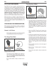
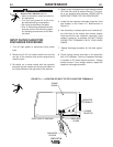
e. Pierce cutting should be done only when nec-
essary. If piercing, angle torch about 30° from
the plane perpendicular to the work piece,
transfer the arc, then bring the torch perpen-
dicular to the work and begin parallel move-
ment.
f. Reduce the number of pilot arc starts without
transferring to the work.
g. Reduce the pilot arc time before transferring
to the work.
h. Set air pressure to recommended setting. A higher
or lower pressure will cause turbulence in the
plasma arc, eroding the orifice of the nozzle tip.
i. Use only Lincoln consumable parts. These
parts are patented and using any other
replacement consumables may cause damage
to the torch or reduce cut quality.
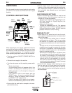
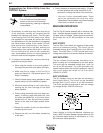
MACHINE INTERFACE
The Pro-Cut 80 comes standard with a machine inter-
face. Interface signals provided include: arc start, arc
initiated, and arc voltage. These signals are accessi-
ble through the 14 pin MS connector on the case
front.
ARC START:
The Arc Start circuit allows for triggering of the power
source to commence cutting. This circuit can be
accessed through pins K and M of the 14 pin MS con-
nector. The circuit has a 17 VDC nominal open circuit
voltage and requires a dry contact closure to activate.
ARC INITIATED:
The Arc Initiated circuit provides information as to
when a cutting arc has transferred to the work piece.
This circuit can be accessed through pins I and J of
the 14 pin MS connector. The circuit provides a dry
contact closure when the arc has transferred. Input to
this circuit should be limited to 0.3 A for either
120VAC or 30VDC.
ARC VOLTAGE:
The Arc Voltage circuit can be used for activating a
torch height control. This circuit can be accessed
through pins D and G of the 14 pin MS connector.
The circuit provides full electrode to work arc voltage
(no voltage divider, 335VDC maximum).
Users wishing to utilize the Machine Interface can
order a K867 Universal Adapter (please adhere to the
pin locations stated above) or manufacture a 14 pin
MS connector cable assembly.
PRO-CUT 80
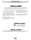
ELECTRIC SHOCK CAN KILL.
• Turn off machine at the disconnect
switch on the front of the machine
before tightening, cleaning or replacing
consumables.
----------------------------------------------------------------------------
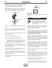
WARNING
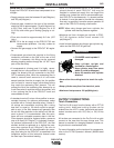
14-PIN BOX RECEPTACLE, FRONT VIEW
J=347
I=348
H
N
G=343
F
E
D=344
C
L
Arc Start
Arc Voltage
Arc Initiated
M=4A
K=2A