


– 22 –
$"%#$
$"% %## '$KK$KK
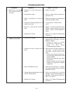
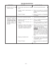
3. Machine does not have
maximum output.
4. Poor welding charac-
teristics. Poor arc
striking with sticking or
“blast-offs”,weld poros-
ity, narrow and ropey
looking bead, or
electrode stubbing into
the plate.
a. Voltage adjust potentiometer leads
open.
b. Voltage adjust potentiometer
defective.
c. Faulty P.C. Board.
a. Poor work or electrode connection.
b. Improper settings for wire feed
speed and volts.
c. Capacitor Bank Contactor not
working.
d. Capacitors in power source output
circuit failed. A failure is indicated
if the small vent plug on the top of
a capacitor is raised or blown out.
e. Opening in feedback circuit.
f. Faulty P.C. Board.
a. Check and repair broken leads.
b. Refer to procedure for checking
Voltage Control Potentiometer on
Machine.
c. Refer to Procedure for Replacing
P.C. Boards.
a. Check and clean all connections.
b. Refer to a welding procedures guide
for proper settings.
c. Refer to the procedure for Checking
the Capacitor Bank Contactor CR3.
d. Replace entire bank of capacitors,
observe correct polarity. Do not
replace individual capacitors.
'"
The liquid electrolyte in
these capacitors is toxic. Avoid con-
tact with any portion of your body.
Clean up vented electrolyte using
rubber gloves and a water damp-
ened cloth. Any electrolyte which
gets on skin, clean with soap and
water.
e. Check wiring and P.C. Board wiring
harness plugs. Pay special attention
to leads 667 and 621.
f. Refer to procedure for replacing P.C.
Board.