


– 32 –
Only qualified persons should install, use or
service this machine.
using the disconnect switch at the fuse box
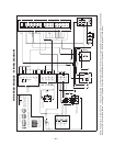
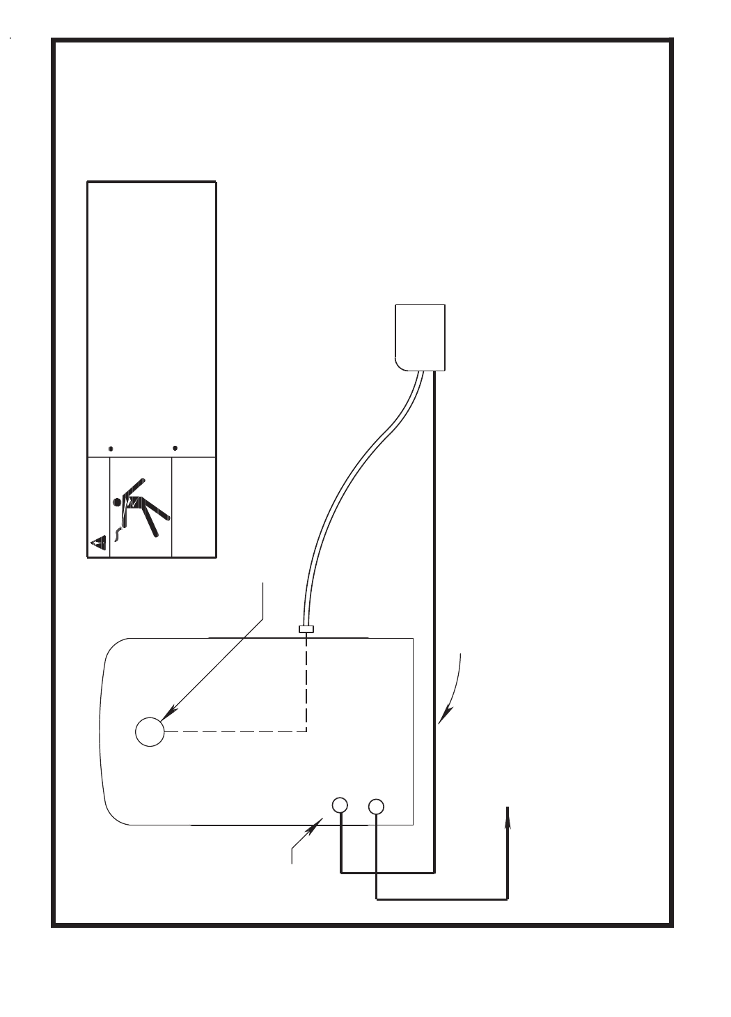
WARNING
Turn off input power to the Welding Power Source
Before connecting the wire feeder.
ELECTRIC
SHOCK
CAN KILL
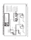
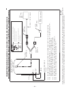
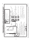
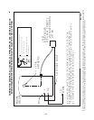
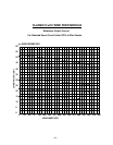
N.A. WELDING CABLE MUST BE SIZED FOR CURRENT AND DUTY CYCLE OF APPLICATION.
N.B. DIAGRAM SHOWS ELECTRODE POSITIVE. TO CHANGE POLARITY, TURN POWER "OFF",
LN-25
WIRE FEEDER
REVERSE ELECTRODE AND WORK CABLES AT POWER SOURCE, SWITCH LN-25 POLARITY SWITCH.
S21039
N.C. WELDER OUTPUT STUDS ON OPPOSITE SIDE FOR CLASSIC II.
TO
WORK
CV-
+
N.C.
14 PIN
AMPHENOL
ELECTRODE CABLE
CONNECTION DIAGRAM: ALL CLASSIC, ALL PIPELINER, SA-250, 350SA & SAE-300
ENGINE WELDERS WITH WIRE FEED MODULE TO LN-25 WITH K444-2 OPTION
WITH K444-2 REMOTE
VOLTAGE CONTROL
OPTION
ENGINE
WELDER
Only qualified persons should install, use or
service this machine.
using the disconnect switch at the fuse box
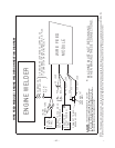
WARNING
Turn off input power to the Welding Power Source
Before connecting the wire feeder.
ELECTRIC
SHOCK
CAN KILL
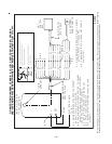
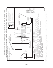
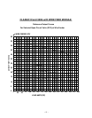
N.A. WELDING CABLE MUST BE SIZED FOR CURRENT AND DUTY CYCLE OF APPLICATION.
N.B. DIAGRAM SHOWS ELECTRODE POSITIVE. TO CHANGE POLARITY, TURN POWER "OFF",
LN-25
WIRE FEE D ER
REVERSE ELECTRODE AND WORK CABLES AT POWER SOURCE, SWITCH LN-25 POLARITY SWITCH.
S 2 1 0 3 9
N.C. WELDER OUTPUT STUDS ON OPPOSITE SIDE FOR CLASSIC II.
TO
WORK
CV-
+
N.C.
14 PIN
AMPHENOL
ELECTROD E CABLE
CONNECTION DIAGRAM: ALL CLASSIC, ALL PIPELINER, SA-250, 350SA & SAE-300
ENGINE WELDERS WITH WIRE FEED MODULE TO LN-25 WITH K444-2 OPTION
WITH K44 4 -2 REM O T E
VOL T AGE CO N T ROL
OPT I ON
ENGINE
WELDER
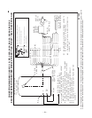
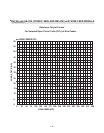
NOTE: This diagram is for reference only. It may not be accurate for all machines covered by this manual. The specific diagram for a particular code is pasted inside the
machine on one of the enclosure panels. If the diagram is illegible, write to the Service Department for a replacement. Give the equipment code number.