


– 9–
Where an engine driven welder is connected to
premises wiring such as that in your home or shop, its
frame must be connected for the system earth
ground. See further connection instructions in the
section entitled “Standby Power Connections” as well
as the article on grounding in the latest U.S. National
Electrical Code and the local code.
In general, if the machine is to be grounded, it should
be connected with a #8 or larger copper wire to a
solid earth ground such as a metal water pipe going
into the ground for at least 10 feet and having no insu-
lated joints or to the metal framework of a building
which has been effectively grounded. The U.S.
National Electrical Code lists a number of alternate
means of grounding electrical equipment. A machine
grounding stud marked with the symbol is provided
on the Generator Mount of the welder.
##)$"&'"#
###"#
3:/638/<+8.
#9<#
#
</8=>+66+>398
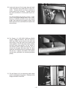
Unpack WFM and check the contents against the
listed items.
$996="/;?3</.
• Large and Small Flat Head Screwdriver
• Pliers
• 3/32” Allen Wrench
• 3/8” Drive Ratchet with Small Extension
• 1/2” Socket
• 9/16” Deep Well Socket
• 3/4” Socket
• 5/16” Nut Driver and Socket
• 1/2” Open End Wrench
• 9/16” Open End Wrench
• Voltmeter
#$$#$"%$#
#+0/>C </-+?>398=
989>+>>/7:>>9?=/>23=/;?3:7/8>?8>36C9?
2+@/>29<9?126C</+.+669:/<+>381+8.7+38>/
8+8-/7+8?+6==?::63/.A3>2C9?<7+-238/$2/C
38-6?./37:9<>+8>=+0/>C:</-+?>398=./>+36/.
/8138/=>+<>3819:/<+>381+8.7+38>/8+8-/
38=><?->398=+8.:+<>=63=>=
+@/+;?+6303/.>/-283-3+8.9>2/7+38>/8+8-/
+8.><9?,6/=299>381A9<5$?<8/8138/900,/09</
A9<538138=3./>2/7+-238/8=97/-+=/=3>7+C
,/8/-/==+<C>9</79@/=+0/>C1?+<.=>9:/<09<7
</;?3</.7+38>/8+8-/"/79@/1?+<.=986CA2/8
8/-/==+<C+8.</:6+-/>2/7A2/8>2/7+38>/
8+8-/</;?3<381</79@+63=-97:6/>/6A+C=?=/
>2/1</+>/=>-+</A2/8A9<53818/+<79@381
:+<>=
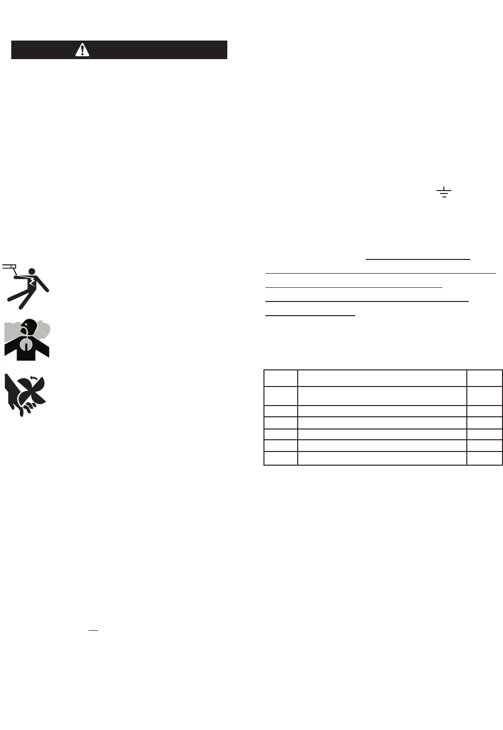
$"# can kill.
• Do not touch electrically live parts such
as output terminals or internal wiring.
(%#$can kill.
• Use in open, well ventilated areas or
vent exhaust outside.
& "$#can injure.
• Do not operate with doors open or
guards off.
• Stop engine before servicing.
• Keep away from moving parts.
86C;?+6303/.:/<=988/6=29?6.38=>+66?=/9<
=/<@3-/>23=/;?3:7/8>
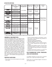
+-238/<9?8.381
Because a portable engine driven welder or generator
creates its own power, it is not necessary to connect
its frame to an earth ground, unless the machine is
connected to premises wiring (your home, shop, etc.)
To prevent dangerous electric shock, other equipment
to which an engine driven welder supplies power
must:
a) Be grounded to the frame of the welder using a
grounded type plug,
9<
b) Be double insulated.
When a welder is mounted on a truck or trailer, its
frame must be securely connected to the metal frame
of the vehicle.
$#" $!$)
1 Control Module Assembly 1
2 Control Panel Assembly 1
3 CV Negative Output Panel Assembly 1
4 Mounting Hardware Packet 1
5 Instruction Manual and Literature 1
6 WFM Nameplate SAE-300
1
'"