


F-53
TROUBLESHOOTING & REPAIR
F-53
TEST PROCEDURE
1. Remove input power to the NA-5
2. Using the 5/16" nutdriver open the
control box PC board access door.
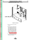
3. Locate the voltage PC board.
Jumper together the "BYPASS" and
“Common” pins on the NA-5 voltage
PC board. See Figure F.6 (On older
voltage boards these pins may be
labeled "B"). This should disable the
shut down circuit.
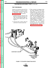
4. Connect to a Lincoln Electric CV
power source per connection dia-
gram. See the
Installation section
of this manual.
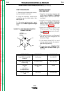
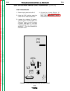
OUT OF VOLTAGE RANGE SHUT DOWN TEST (Continued)
NA-5
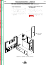
FIGURE F.6 VOLTAGE BOARD AND PIN LOCATIONS
NA-5
VOLTAGE
G1556-[ ]
BYPASS
COM
AUTO
JUMPER
TOGETHER
1/8 AMP FUSE
Return to Section TOC Return to Section TOC Return to Section TOC Return to Section TOC
Return to Master TOC Return to Master TOC Return to Master TOC Return to Master TOC