


E-3
THEORY OF OPERATION
E-3
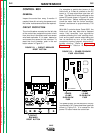
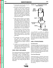
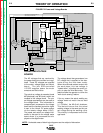
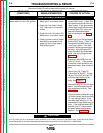
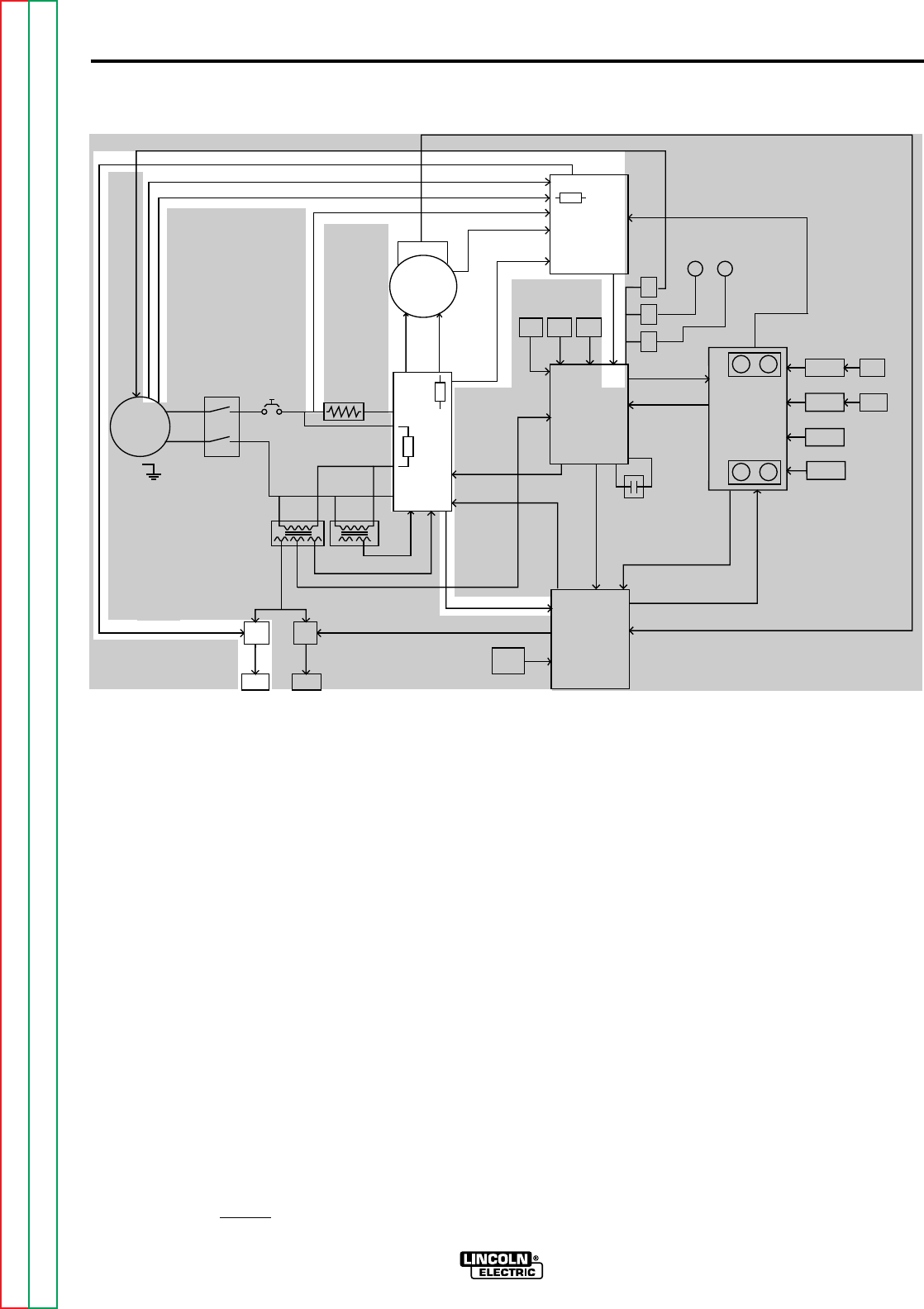
POWER AND VOLTAGE
BOARDS
The AC voltages that are received by
the power board are rectified and regu-
lated. These DC voltages are supplied
to the motor, voltage board and control
board. The two SCR-controlled
115VDC supplies power the motor
armature and field circuits.
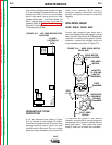
The actual arc voltage is sensed at leads
#67(electrode) and #21(work) which are
coupled to the voltage board. The pre-
set voltage requirements are also sent to
the voltage board. This information is
compared and processed on the voltage
board and the resultant correction signal
is sent to the Lincoln CV power source
via the remote voltage leads (A,B,C).
The preset and actual arc voltage infor-
mation is also sent to the voltage meter
board where it is processed and dis-
played on the digital meter.
The voltage board also generates a low
DC voltage that is applied to the elec-
trode during the inch down mode.
When the electrode makes contact with
the work piece, this low voltage is
"loaded down", signaling the control cir-
cuitry to stop the wire feed motor. This
feature allows the operator to utilize the
"work touch sensing" feature.
If for any reason the actual welding arc
voltage does not match the set weld
voltage
(+/- 0.5Volts) the NA-5 will shutdown.
This feature insures that the actual
welding voltage is the same as the pre-
set voltage during the welding cycle.
This circuitry is incorporated on the volt-
age board.
FIGURE E.2 Power and Voltage Boards
NA-5
F1
A
R
M
A
T
U
R
E
F
I
E
L
D
V
O
L
T
A
G
E
V
O
L
T
A
G
E
T1 T2
OPTIONAL
START
BOARD
OPTIONAL
CRATER
BOARD
OPTIONAL
WELD
TIMER
BURNBACK
TIMER
VOLTAGE
BOARD
METER
BOARD
SPEED
VOLT
METER
BOARD
DIGITAL
METER
DIGITAL
METER
MOTOR
LOGIC
BOARD
CONTROL
BOARD
P
O
W
E
R
B
O
A
R
D
P
R
O
C
E
D
U
R
E
B
O
A
R
D
TACH
INCH
DOWN
SWITCH
STOP
SWITCH
START
SWITCH
WELD
CURRENT
REED SWITCH
CR
1
CR
2
CR
3
FLUX
RECEPTACLE
TRAVEL
RECEPTACLE
CONTACTOR CLOSURE (#2 AND #4)
REMOTE VOLTAGE CONTROL (A, B, C)
WORK SENSING (#21)
TACH FEEDBACK (MOTOR RPM)
DC SUPPLY VOLTAGE
10VDC REFERENCEVOLTAGE
DC VOLTAGE
S
I
G
N
A
L
INPUT
POWER
SWITCH
CIRCUIT
BREAKER
R1(2 OHMS)
MOTOR
G
A
T
E
S
I
G
N
A
L
S
CONTROL
CABLE
RECEPTACLE
TACH FEEDBACK (MOTOR RPM)
115VAC
36VAC (18+18VAC)
22VAC
1
V
A
C
0
D
C
S
U
P
P
L
Y
V
O
L
T
A
G
E
SIGNAL
A
R
C
V
O
L
T
A
G
E
S
H
U
T
D
O
W
N
A
N
D
INCH
UP
SWITCH
STRIKE/WELD PROCEDURE
ENABLE
FIELD
ARMATURE
F
E
E
D
E
N
A
B
L
E
DIRECTION
ARC VOLTS (SET & ACTUAL)
WIRE FEED SPEED (SET & ACTUAL)
E
L
E
C
T
R
ODE SENSING
(#67)
115
VAC
WELD
VOLTS SPEED
VOLTS SPEED
STRIKE
115VAC
#31
#32
1/2 AMP
F501
SET SPEED
SET VOLTAGE
START
TIMER
CRATER
TIMER
F2
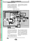
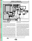
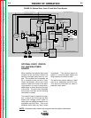
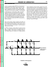
NOTE: Unshaded areas of block logic diagrams are the subject of discussion.
Return to Section TOC Return to Section TOC Return to Section TOC Return to Section TOC
Return to Master TOC Return to Master TOC Return to Master TOC Return to Master TOC